ZyXEL Omni TA 128 User Guide - Page 21
Power On and Self Diagnostics - cycles
 |
View all ZyXEL Omni TA 128 manuals
Add to My Manuals
Save this manual to your list of manuals |
Page 21 highlights
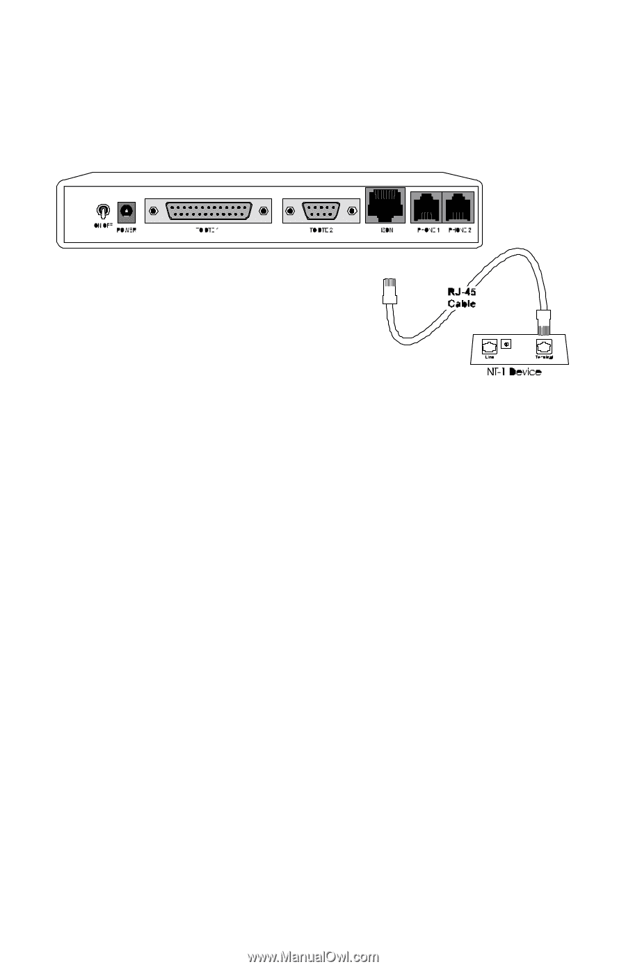
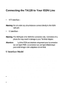
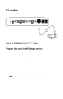
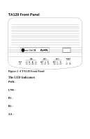
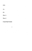
S/T Interface If you have purchased the TA128 S/T model, you will need an NT1 device to connect to the network. Figure 2 -3 Hooking Up an NT-1 Device Power On and Self Diagnostics Once you have completed all of the installation steps above, flip the TA128's On/Off switch to the ON (up) position. The unit should cycle through a self test sequence, where you should see a series of LED lights blinking (LED, B1, B2, AA). After this cycle is complete, the PWR light should stay on. If the test routine fails, the LNK LED flashes. Refer to Chapter 15 , for more information on self-tests and error codes. If you have a communication program loaded and active (connected to the same serial port as the TA128), you should see the DTR LED should be ON after the self test. 9
-
 1
1 -
2
-
3
-
4
-
5
-
6
-
7
-
8
-
9
-
10
-
11
-
12
-
13
-
14
-
15
-
 16
16 -
 17
17 -
 18
18 -
 19
19 -
 20
20 -
 21
21 -
 22
22 -
 23
23 -
 24
24 -
 25
25 -
 26
26 -
27
-
28
-
29
-
30
-
31
-
32
-
33
-
34
-
35
-
36
-
37
-
38
-
39
-
40
-
41
-
42
-
43
-
44
-
45
-
46
-
47
-
48
-
49
-
50
-
51
-
52
-
53
-
54
-
55
-
56
-
57
-
58
-
59
-
60
-
61
-
62
-
63
-
64
-
65
-
66
-
67
-
68
-
69
-
70
-
71
-
72
-
73
-
74
-
75
-
76
-
77
-
78
-
79
-
80
-
81
-
82
-
83
-
84
-
85
-
86
-
87
-
88
-
89
-
90
-
91
-
92
-
93
-
94
-
95
-
96
-
97
-
98
-
99
-
100
-
101
-
102
-
103
-
104
-
105
-
106
-
107
-
108
-
109
-
110
-
111
-
112
-
113
-
114
-
115
-
116
-
117
-
118
-
119
-
120
-
121
-
122
-
123
-
124
-
125
-
126
-
127
-
128
-
129
-
130
-
131
-
132
-
133
-
134
-
135
-
136
-
137
-
138
-
139
-
140
-
141
-
142
-
143
-
144
-
145
-
146
-
147
-
148
-
149
-
150
-
151
-
152
-
153
-
154
-
155
-
156
-
157
-
158
-
159
-
160
-
161
-
162
-
163
-
164
-
165
-
166
-
167
-
168
-
169
-
170
-
171
-
172
-
173
 |
 |