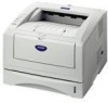
Brother International HL 5030 Service Manual - Page 5

Theory Of Operation, Control Panel Operation, Network Functions - reset

Page 5 highlights

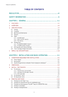
HL-5030/5040/5050/5070N SERVICE MANUAL 4.6 Printing on Both Sides of the Paper (manual duplex printing 2-24 4.7 Guidelines for printing on both sides of the paper 2-26 4.8 Paper orientation for printing on both sides of the paper 2-27 5. CONTROL PANEL OPERATION 2-28 5.1 Control Panel Buttons & LED functions 2-28 5.1.1 LEDs ...2-28 5.1.2 Control Panel Buttons ...2-28 5.2 LED Indiations ...2-29 5.3 Service call indications 2-31 5.4 Control Panel Button Operations 2-32 5.5 Other Control Features 2-33 5.5.1 Sleep mode...2-33 5.5.2 Print a test page...2-34 5.5.3 Print Settings...2-34 5.5.4 Print fonts (For HL-5040, HL-5050 and HL-5070N 2-35 6. NETWORK FUNCTIONS 2-36 6.1 LED functions ...2-36 6.2 Network Factory default setting (For HL-5070N 2-36 7. PAPER CASSETTE INFORMATION (FOR EUROPE ONLY 2-37 CHAPTER 3 THEORY OF OPERATION 3-1 1. ELECTRONICS...3-1 1.1 General Block Diagram ...3-1 1.2 Main PCB Block Diagram 3-2 1.3 Main PCB...3-3 1.3.1 CPU ...3-3 1.3.2 USB...3-5 1.3.3 IEEE 1284...3-6 1.3.4 Network Interface ...3-7 1.3.5 ROM...3-8 1.3.6 Flash ROM ...3-9 1.3.7 SDRAM ...3-10 1.3.8 Optional RAM...3-11 1.3.9 EEPROM...3-13 1.3.10 Reset Circuit ...3-13 1.3.11 Engine I/O ...3-14 1.3.12 Panel I/O ...3-14 1.3.13 Video I/O ...3-15 1.3.14 Power Supply ...3-16 1.4 Engine PCB ...3-17 1.5 Power Supply...3-18 1.5.1 Low-voltage Power Supply 3-18 1.5.2 High-voltage Power Supply 3-19 2. MECHANICS ...3-20 2.1 Overview of Printing Mechanism 3-20 2.2 Paper Transfer...3-21 2.2.1 Paper supply ...3-21 2.2.2 Paper registration...3-21 iii

  • 1
  • 2
  • 3
  • 4
  • 5
  • 6
  • 7
  • 8
  • 9
  • 10
  • 11
  • 12
  • 13
  • 14
  • 15
  • 16
  • 17
  • 18
  • 19
  • 20
  • 21
  • 22
  • 23
  • 24
  • 25
  • 26
  • 27
  • 28
  • 29
  • 30
  • 31
  • 32
  • 33
  • 34
  • 35
  • 36
  • 37
  • 38
  • 39
  • 40
  • 41
  • 42
  • 43
  • 44
  • 45
  • 46
  • 47
  • 48
  • 49
  • 50
  • 51
  • 52
  • 53
  • 54
  • 55
  • 56
  • 57
  • 58
  • 59
  • 60
  • 61
  • 62
  • 63
  • 64
  • 65
  • 66
  • 67
  • 68
  • 69
  • 70
  • 71
  • 72
  • 73
  • 74
  • 75
  • 76
  • 77
  • 78
  • 79
  • 80
  • 81
  • 82
  • 83
  • 84
  • 85
  • 86
  • 87
  • 88
  • 89
  • 90
  • 91
  • 92
  • 93
  • 94
  • 95
  • 96
  • 97
  • 98
  • 99
  • 100
  • 101
  • 102
  • 103
  • 104
  • 105
  • 106
  • 107
  • 108
  • 109
  • 110
  • 111
  • 112
  • 113
  • 114
  • 115
  • 116
  • 117
  • 118
  • 119
  • 120
  • 121
  • 122
  • 123
  • 124
  • 125
  • 126
  • 127
  • 128
  • 129
  • 130
  • 131
  • 132
  • 133
  • 134
  • 135
  • 136
  • 137
  • 138
  • 139
  • 140
  • 141
  • 142
  • 143
  • 144
  • 145
  • 146
  • 147
  • 148
  • 149
  • 150
  • 151
  • 152
  • 153
  • 154
  • 155
  • 156
  • 157
  • 158
  • 159
  • 160
  • 161
  • 162
  • 163
  • 164
  • 165
  • 166
  • 167
  • 168
  • 169
  • 170
  • 171
  • 172
  • 173
  • 174
  • 175
  • 176
  • 177
  • 178
  • 179
  • 180
  • 181
  • 182
  • 183
  • 184
  • 185
  • 186
  • 187
  • 188
  • 189
  • 190
  • 191
  • 192
  • 193
  • 194
  • 195
  • 196
  • 197
  • 198
  • 199
  • 200
  • 201
  • 202
  • 203
  • 204
  • 205
  • 206
  • 207
  • 208
  • 209
  • 210
  • 211
  • 212
  • 213
  • 214
  • 215
  • 216
  • 217
  • 218
  • 219
  • 220
  • 221
  • 222
  • 223
  • 224
  • 225
  • 226
  • 227
  • 228
  • 229
  • 230
  • 231
  • 232
  • 233
  • 234
  • 235
  • 236
  • 237
  • 238
  • 239
  • 240
  • 241
  • 242
  • 243
  • 244
  • 245
  • 246
  • 247
  • 248
  • 249
  • 250
  • 251
  • 252
  • 253
  • 254
  • 255
  • 256
  • 257
  • 258
  • 259
  • 260
  • 261
  • 262
  • 263
  • 264
  • 265

HL-5030/5040/5050/5070N SERVICE MANUAL
iii
4.6
Printing on Both Sides of the Paper (manual duplex printing)
........................................
2-24
4.7
Guidelines for printing on both sides of the paper
..........................................................
2-26
4.8
Paper orientation for printing on both sides of the paper
................................................
2-27
5.
CONTROL PANEL OPERATION
..........................................................................
2-28
5.1
Control Panel Buttons & LED functions
..........................................................................
2-28
5.1.1 LEDs
.................................................................................................................................
2-28
5.1.2 Control Panel Buttons
.......................................................................................................
2-28
5.2
LED Indiations
................................................................................................................
2-29
5.3
Service call indications
...................................................................................................
2-31
5.4
Control Panel Button Operations
....................................................................................
2-32
5.5
Other Control Features
...................................................................................................
2-33
5.5.1 Sleep mode
.......................................................................................................................
2-33
5.5.2
Print a test page
................................................................................................................
2-34
5.5.3 Print Settings
.....................................................................................................................
2-34
5.5.4
Print fonts (For HL-5040, HL-5050 and HL-5070N)
..........................................................
2-35
6.
NETWORK FUNCTIONS
......................................................................................
2-36
6.1
LED functions
.................................................................................................................
2-36
6.2
Network Factory default setting (For HL-5070N)
............................................................
2-36
7.
PAPER CASSETTE INFORMATION (FOR EUROPE ONLY)
...............................
2-37
CHAPTER 3
THEORY OF OPERATION
.................................................
3-1
1.
ELECTRONICS
.......................................................................................................
3-1
1.1
General Block Diagram
....................................................................................................
3-1
1.2
Main PCB Block Diagram
.................................................................................................
3-2
1.3
Main PCB
..........................................................................................................................
3-3
1.3.1 CPU
....................................................................................................................................
3-3
1.3.2 USB
.....................................................................................................................................
3-5
1.3.3 IEEE 1284
...........................................................................................................................
3-6
1.3.4 Network Interface
................................................................................................................
3-7
1.3.5 ROM
....................................................................................................................................
3-8
1.3.6 Flash ROM
..........................................................................................................................
3-9
1.3.7 SDRAM
.............................................................................................................................
3-10
1.3.8 Optional RAM
....................................................................................................................
3-11
1.3.9 EEPROM
...........................................................................................................................
3-13
1.3.10 Reset Circuit
.....................................................................................................................
3-13
1.3.11 Engine I/O
.........................................................................................................................
3-14
1.3.12 Panel I/O
...........................................................................................................................
3-14
1.3.13 Video I/O
...........................................................................................................................
3-15
1.3.14 Power Supply
....................................................................................................................
3-16
1.4
Engine PCB
....................................................................................................................
3-17
1.5
Power Supply
..................................................................................................................
3-18
1.5.1 Low-voltage Power Supply
................................................................................................
3-18
1.5.2 High-voltage Power Supply
...............................................................................................
3-19
2.
MECHANICS
.........................................................................................................
3-20
2.1
Overview of Printing Mechanism
....................................................................................
3-20
2.2
Paper Transfer
................................................................................................................
3-21
2.2.1 Paper supply
.....................................................................................................................
3-21
2.2.2 Paper registration
..............................................................................................................
3-21