Cisco WS-C2980G-A Software Guide - Page 428
Fan tray-25 W
 |
UPC - 746320423555
View all Cisco WS-C2980G-A manuals
Add to My Manuals
Save this manual to your list of manuals |
Page 428 highlights
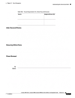
Understanding How Power Management Works on the Catalyst 4006 Switch Chapter 28 Power Management These scenarios initiate the five-minute evaluation countdown timer. When this timer runs out, the switch tries to resolve this power limitation by evaluating the type and number of modules that are installed. The evaluation process may require several cycles to stabilize the chassis' power usage. During the evaluation cycle, the modules are removed and reinserted, thus disrupting network connectivity. The switch reactivates only the modules that it is able to support with the limited power available and leaves the remaining modules in reset mode. The supervisor engine always remains enabled. Modules that are placed in reset mode still consume some power. If the chassis module combination and the modules in reset mode still require more power than is available, the timer starts again, and additional modules are placed into reset mode until the power usage is stable. If the power requirement of the active modules and the modules in reset mode do not exceed the available power, the switch is stable and no more evaluation cycles are run, until something again causes insufficient power usage. One or two cycles are required to stabilize the switch. If you configure the chassis correctly, the switch does not enter the evaluation cycle. Note If all three power supplies are installed in your Catalyst 4006 switch and you set 1+1 redundancy mode but later add additional modules that exceed the power available, the timer starts again. The switch may require several evaluation cycles to stabilize the system.You can either remove the extra modules or change the power budget to 2+1 redundancy mode. If you change to 2+1 redundancy mode, each module in reset mode is brought up one at a time to an operational state. If you use a 400 W power supply and a 650 W power supply in your switch, the switch acts as if there were two 400 W power supplies. If you have one 400 W power supply and one 650 W power supply in 1+1 redundancy mode, and a second 650 W power supply is set as the backup, the switch acts as if there were a total of 400 W. If the 400 W power supply fails, the backup 650 W power supply comes into service; however, the switch still has only 400 W available. You must remove the failed 400 W power supply so that the switch can use the available 650 W. The following configuration requires a minimum of 395 W: • WS-X4013 supervisor engine-110 W • Four WS-X4148-RJ modules-65 W each (260 W total-the optimized module configuration) • Fan tray-25 W The following configuration requires more power than a single 400 W power supply can provide. It requires 445 W and cannot be used in 1+1 redundancy mode for a 400 W power supply. A single 650 W power supply provides enough power for 1+1 redundancy mode for this configuration. • WS-X4013 supervisor engine-110 W • Two WS-X4148-RJ modules in slots 2 and 3-65 W each (130 W total) • Two WS-X4448-GB-LX modules in slots 4 and 5-90 W each (180 W total) • Fan tray-25 W The following configuration requires more power than either a single 400 W or 650 W power supply can provide. It requires 735 W and cannot be used in 1+1 redundancy mode for either a 400 W or 650 W power supply. • WS-X4013 supervisor engine-110 W • Five 48-port 100BASE-FX modules in slots 2 through 6-120 W each (600 W total) • Fan tray-25 W 28-8 Catalyst 4500 Series, Catalyst 2948G, Catalyst 2980G Switches Software Configuration Guide-Release 8.1 78-15486-01
-
 1
1 -
2
-
3
-
4
-
5
-
6
-
7
-
8
-
9
-
10
-
11
-
12
-
13
-
14
-
15
-
16
-
17
-
18
-
19
-
20
-
21
-
22
-
23
-
24
-
25
-
26
-
27
-
28
-
29
-
30
-
31
-
32
-
33
-
34
-
35
-
36
-
37
-
38
-
39
-
40
-
41
-
42
-
43
-
44
-
45
-
46
-
47
-
48
-
49
-
50
-
51
-
52
-
53
-
54
-
55
-
56
-
57
-
58
-
59
-
60
-
61
-
62
-
63
-
64
-
65
-
66
-
67
-
68
-
69
-
70
-
71
-
72
-
73
-
74
-
75
-
76
-
77
-
78
-
79
-
80
-
81
-
82
-
83
-
84
-
85
-
86
-
87
-
88
-
89
-
90
-
91
-
92
-
93
-
94
-
95
-
96
-
97
-
98
-
99
-
100
-
101
-
102
-
103
-
104
-
105
-
106
-
107
-
108
-
109
-
110
-
111
-
112
-
113
-
114
-
115
-
116
-
117
-
118
-
119
-
120
-
121
-
122
-
123
-
124
-
125
-
126
-
127
-
128
-
129
-
130
-
131
-
132
-
133
-
134
-
135
-
136
-
137
-
138
-
139
-
140
-
141
-
142
-
143
-
144
-
145
-
146
-
147
-
148
-
149
-
150
-
151
-
152
-
153
-
154
-
155
-
156
-
157
-
158
-
159
-
160
-
161
-
162
-
163
-
164
-
165
-
166
-
167
-
168
-
169
-
170
-
171
-
172
-
173
-
174
-
175
-
176
-
177
-
178
-
179
-
180
-
181
-
182
-
183
-
184
-
185
-
186
-
187
-
188
-
189
-
190
-
191
-
192
-
193
-
194
-
195
-
196
-
197
-
198
-
199
-
200
-
201
-
202
-
203
-
204
-
205
-
206
-
207
-
208
-
209
-
210
-
211
-
212
-
213
-
214
-
215
-
216
-
217
-
218
-
219
-
220
-
221
-
222
-
223
-
224
-
225
-
226
-
227
-
228
-
229
-
230
-
231
-
232
-
233
-
234
-
235
-
236
-
237
-
238
-
239
-
240
-
241
-
242
-
243
-
244
-
245
-
246
-
247
-
248
-
249
-
250
-
251
-
252
-
253
-
254
-
255
-
256
-
257
-
258
-
259
-
260
-
261
-
262
-
263
-
264
-
265
-
266
-
267
-
268
-
269
-
270
-
271
-
272
-
273
-
274
-
275
-
276
-
277
-
278
-
279
-
280
-
281
-
282
-
283
-
284
-
285
-
286
-
287
-
288
-
289
-
290
-
291
-
292
-
293
-
294
-
295
-
296
-
297
-
298
-
299
-
300
-
301
-
302
-
303
-
304
-
305
-
306
-
307
-
308
-
309
-
310
-
311
-
312
-
313
-
314
-
315
-
316
-
317
-
318
-
319
-
320
-
321
-
322
-
323
-
324
-
325
-
326
-
327
-
328
-
329
-
330
-
331
-
332
-
333
-
334
-
335
-
336
-
337
-
338
-
339
-
340
-
341
-
342
-
343
-
344
-
345
-
346
-
347
-
348
-
349
-
350
-
351
-
352
-
353
-
354
-
355
-
356
-
357
-
358
-
359
-
360
-
361
-
362
-
363
-
364
-
365
-
366
-
367
-
368
-
369
-
370
-
371
-
372
-
373
-
374
-
375
-
376
-
377
-
378
-
379
-
380
-
381
-
382
-
383
-
384
-
385
-
386
-
387
-
388
-
389
-
390
-
391
-
392
-
393
-
394
-
395
-
396
-
397
-
398
-
399
-
400
-
401
-
402
-
403
-
404
-
405
-
406
-
407
-
408
-
409
-
410
-
411
-
412
-
413
-
414
-
415
-
416
-
417
-
418
-
419
-
420
-
421
-
422
-
 423
423 -
 424
424 -
 425
425 -
 426
426 -
 427
427 -
 428
428 -
 429
429 -
 430
430 -
 431
431 -
 432
432 -
 433
433 -
434
-
435
-
436
-
437
-
438
-
439
-
440
-
441
-
442
-
443
-
444
-
445
-
446
-
447
-
448
-
449
-
450
-
451
-
452
-
453
-
454
-
455
-
456
-
457
-
458
-
459
-
460
-
461
-
462
-
463
-
464
-
465
-
466
-
467
-
468
-
469
-
470
-
471
-
472
-
473
-
474
-
475
-
476
-
477
-
478
-
479
-
480
-
481
-
482
-
483
-
484
-
485
-
486
-
487
-
488
-
489
-
490
-
491
-
492
-
493
-
494
-
495
-
496
-
497
-
498
-
499
-
500
-
501
-
502
-
503
-
504
-
505
-
506
-
507
-
508
-
509
-
510
-
511
-
512
-
513
-
514
-
515
-
516
-
517
-
518
-
519
-
520
-
521
-
522
-
523
-
524
-
525
-
526
-
527
-
528
-
529
-
530
-
531
-
532
-
533
-
534
-
535
-
536
-
537
-
538
-
539
-
540
-
541
-
542
-
543
-
544
-
545
-
546
-
547
-
548
-
549
-
550
-
551
-
552
-
553
-
554
-
555
-
556
-
557
-
558
-
559
-
560
-
561
-
562
-
563
-
564
-
565
-
566
-
567
-
568
-
569
-
570
-
571
-
572
-
573
-
574
-
575
-
576
-
577
-
578
-
579
-
580
-
581
-
582
-
583
-
584
-
585
-
586
-
587
-
588
-
589
-
590
-
591
-
592
-
593
-
594
-
595
-
596
-
597
-
598
-
599
-
600
-
601
-
602
-
603
-
604
-
605
-
606
-
607
-
608
-
609
-
610
-
611
-
612
 |
 |
