Creative CT4180 Getting Started Guide - Page 50
Telephone Answering Device Connector Pin Assignmen..., Wave Blaster Connector Pin Assignments
 |
View all Creative CT4180 manuals
Add to My Manuals
Save this manual to your list of manuals |
Page 50 highlights
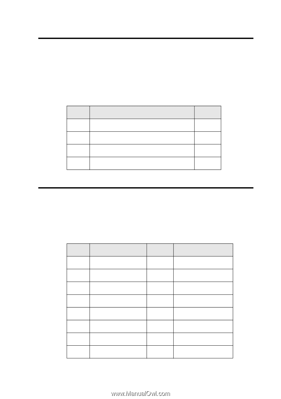
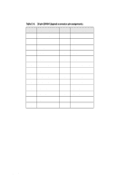
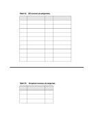
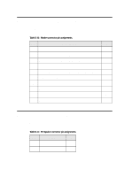
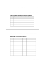
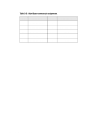
Telephone Answering Device Connector Pin Assignments The Telephone Answering Device connector has the following pin assignments as shown in Table D-14. Table D-14: Telephone Answering Device connector pin assignments. Pin Description I/O 1 Mono Line-In from modem. In 2 Analog Ground - 3 Analog Ground - 4 Microphone output to modem. Out Wave Blaster Connector Pin Assignments The Wave Blaster connector has the following pin descriptions as shown in Table D-15. Table D-15: Wave Blaster connector pin assignments. Pin Description Pin 1 Digital Ground 2 3 Digital Ground 4 5 Digital Ground 6 7 Digital Ground 8 9 Digital Ground 10 11 Digital Ground 12 13 NC 14 15 Analog Ground 16 Description NC MIDI Output VCC MIDI Input VCC NC VCC NC Hardware Information D-11
-
 1
1 -
2
-
3
-
4
-
5
-
6
-
7
-
8
-
9
-
10
-
11
-
12
-
13
-
14
-
15
-
16
-
17
-
18
-
19
-
20
-
21
-
22
-
23
-
24
-
25
-
26
-
27
-
28
-
29
-
30
-
31
-
32
-
33
-
34
-
35
-
36
-
37
-
38
-
39
-
40
-
41
-
42
-
43
-
44
-
 45
45 -
 46
46 -
 47
47 -
 48
48 -
 49
49 -
 50
50 -
 51
51 -
 52
52 -
 53
53 -
 54
54 -
 55
55 -
56
-
57
-
58
-
59
-
60
-
61
-
62
-
63
-
64
-
65
-
66
-
67
-
68
-
69
-
70
-
71
-
72
-
73
-
74
-
75
-
76
-
77
-
78
-
79
-
80
-
81
-
82
-
83
-
84
-
85
-
86
-
87
-
88
-
89
-
90
-
91
-
92
-
93
-
94
-
95
 |
 |