Dell Dimension 8200 Dell Dimension 8200 Systems Solutions Guide - Page 79
on the ends of the module until it snaps into place.
 |
View all Dell Dimension 8200 manuals
Add to My Manuals
Save this manual to your list of manuals |
Page 79 highlights
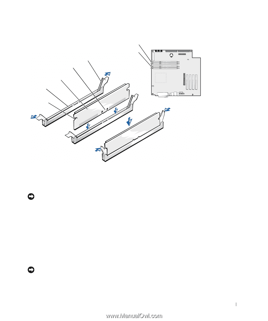
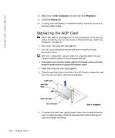
memory connectors RIMM3 and RIMM4 memory connectors RIMM1 and RIMM2 securing clips (2) notches (2) memory or continuity module connector cutouts (2) step 6 step 7 step 8 7 Align the notches on the bottom of the module with the crossbars in the connector. NOTICE: To avoid breaking the memory module, do not press near the middle of the module. 8 Insert the module straight down into the connector, ensuring that it fits into the vertical guides at each end of the connector. Press firmly on the ends of the module until it snaps into place. If you insert the module correctly, the securing clips snap into the cutouts at each end of the module. 9 Close the computer cover (see page 90). 10 Connect your computer and devices to their electrical outlets, and turn them on. NOTICE: To connect a network cable, first plug the cable into the network wall jack and then plug it into the computer. Addi ng Part s 79
-
 1
1 -
2
-
3
-
4
-
5
-
6
-
7
-
8
-
9
-
10
-
11
-
12
-
13
-
14
-
15
-
16
-
17
-
18
-
19
-
20
-
21
-
22
-
23
-
24
-
25
-
26
-
27
-
28
-
29
-
30
-
31
-
32
-
33
-
34
-
35
-
36
-
37
-
38
-
39
-
40
-
41
-
42
-
43
-
44
-
45
-
46
-
47
-
48
-
49
-
50
-
51
-
52
-
53
-
54
-
55
-
56
-
57
-
58
-
59
-
60
-
61
-
62
-
63
-
64
-
65
-
66
-
67
-
68
-
69
-
70
-
71
-
72
-
73
-
 74
74 -
 75
75 -
 76
76 -
 77
77 -
 78
78 -
 79
79 -
 80
80 -
 81
81 -
 82
82 -
 83
83 -
 84
84 -
85
-
86
-
87
-
88
-
89
-
90
-
91
-
92
-
93
-
94
-
95
-
96
-
97
-
98
-
99
-
100
-
101
-
102
-
103
-
104
-
105
-
106
-
107
-
108
-
109
-
110
-
111
-
112
-
113
-
114
-
115
-
116
-
117
-
118
-
119
-
120
-
121
-
122
-
123
-
124
-
125
-
126
-
127
-
128
-
129
-
130
-
131
-
132
-
133
-
134
-
135
-
136
-
137
-
138
-
139
-
140
-
141
-
142
-
143
-
144
-
145
-
146
-
147
-
148
-
149
-
150
 |
 |