Dell PowerEdge 840 Hardware Owner's Manual (PDF) - Page 119
Table 6-2., System Board Connectors, Connector, Description, FRONT_PANEL - cpu
 |
View all Dell PowerEdge 840 manuals
Add to My Manuals
Save this manual to your list of manuals |
Page 119 highlights
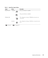
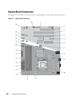
Table 6-2. System Board Connectors Item Connector 1 RAC_CONN 2 SLOT_5 3 SLOT_4 4 SLOT_3 5 SLOT_2 6 SLOT_1 7 BATTERY 8 HD 9 BACK_FAN 10 CPU 11 12V 12 PWR_CONN 13 IDE 14 FDD 15 DIMM2_ B 16 DIMM1_ B 17 DIMM2_ A 18 DIMM2_ A 19 FRONT_PANEL 20 USB 21 SATA_0 22 SATA_1 23 SATA_2 24 SATA_3 25 FRONT_FAN 26 BP_I2C Description Connector for the remote access controller (RAC) PCI 32-bit, 33-MHz (5-V) expansion slot connector PCI-X 64-bit, 133-MHz (3.3-V) expansion slot connector PCI-X 64-bit, 133-MHz (3.3-V) expansion slot connector PCI-Express (x1) expansion slot connector PCI-Express (x8) expansion slot connector Connector for the 3.0-V coin battery Hard drive LED activity connector Fan power connector Processor connector Power connector Power connector IDE optical device connector Diskette drive connector Memory module connector Memory module connector Memory module connector Memory module connector Control panel connector USB 2.0-compliant connector SATA connector SATA connector SATA connector SATA connector Fan power connector Connector for the baseboard management controller (BMC) inter-IC (I2C) cable for the optional SCSI backplane Jumpers and Connectors 119
-
 1
1 -
2
-
3
-
4
-
5
-
6
-
7
-
8
-
9
-
10
-
11
-
12
-
13
-
14
-
15
-
16
-
17
-
18
-
19
-
20
-
21
-
22
-
23
-
24
-
25
-
26
-
27
-
28
-
29
-
30
-
31
-
32
-
33
-
34
-
35
-
36
-
37
-
38
-
39
-
40
-
41
-
42
-
43
-
44
-
45
-
46
-
47
-
48
-
49
-
50
-
51
-
52
-
53
-
54
-
55
-
56
-
57
-
58
-
59
-
60
-
61
-
62
-
63
-
64
-
65
-
66
-
67
-
68
-
69
-
70
-
71
-
72
-
73
-
74
-
75
-
76
-
77
-
78
-
79
-
80
-
81
-
82
-
83
-
84
-
85
-
86
-
87
-
88
-
89
-
90
-
91
-
92
-
93
-
94
-
95
-
96
-
97
-
98
-
99
-
100
-
101
-
102
-
103
-
104
-
105
-
106
-
107
-
108
-
109
-
110
-
111
-
112
-
113
-
 114
114 -
 115
115 -
 116
116 -
 117
117 -
 118
118 -
 119
119 -
 120
120 -
 121
121 -
 122
122 -
 123
123 -
 124
124 -
125
-
126
-
127
-
128
-
129
-
130
-
131
-
132
-
133
-
134
-
135
-
136
-
137
-
138
-
139
-
140
-
141
-
142
-
143
-
144
-
145
-
146
-
147
-
148
-
149
-
150
-
151
-
152
-
153
-
154
-
155
-
156
-
157
-
158
 |
 |
