Dell PowerEdge 840 Hardware Owner's Manual (PDF) - Page 72
Installing an Expansion Card, Remove the filler bracket from the expansion slot.
 |
View all Dell PowerEdge 840 manuals
Add to My Manuals
Save this manual to your list of manuals |
Page 72 highlights
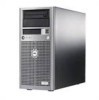
Figure 3-18. Expansion Slots 1 2 3 4 5 1 SLOT_5 - PCI 32-bit, 33-MHz (5-V) 4 SLOT_2 - x1 lane width PCI-Express 2 SLOT_4 - PCI-X 64-bit, 133-MHz (3.3-V) 5 SLOT_1 - x8 lane width PCI-Express 3 SLOT_3 - PCI-X 64-bit, 133-MHz (3.3-V) Installing an Expansion Card CAUTION: Only trained service technicians are authorized to remove the system cover and access any of the components inside the system. Before performing any procedure, see your Product Information Guide for complete information about safety precautions, working inside the computer, and protecting against electrostatic discharge. 1 Unpack the expansion card, and prepare it for installation. For instructions, see the documentation that accompanied the card. 2 Turn off the system, including any attached peripherals, and disconnect the system from the electrical outlet. 3 Open the system. See "Opening the System" on page 43. 4 Remove the filler bracket from the expansion slot. 5 Install the expansion card. See Figure 3-19. a Position the expansion card so that the card-edge connector aligns with the expansion-card connector on the system board. b Insert the card-edge connector firmly into the expansion-card connector until the card is fully seated. c Install the screw that secures the expansion-card bracket to the back panel. 72 Installing System Components
-
 1
1 -
2
-
3
-
4
-
5
-
6
-
7
-
8
-
9
-
10
-
11
-
12
-
13
-
14
-
15
-
16
-
17
-
18
-
19
-
20
-
21
-
22
-
23
-
24
-
25
-
26
-
27
-
28
-
29
-
30
-
31
-
32
-
33
-
34
-
35
-
36
-
37
-
38
-
39
-
40
-
41
-
42
-
43
-
44
-
45
-
46
-
47
-
48
-
49
-
50
-
51
-
52
-
53
-
54
-
55
-
56
-
57
-
58
-
59
-
60
-
61
-
62
-
63
-
64
-
65
-
66
-
 67
67 -
 68
68 -
 69
69 -
 70
70 -
 71
71 -
 72
72 -
 73
73 -
 74
74 -
 75
75 -
 76
76 -
 77
77 -
78
-
79
-
80
-
81
-
82
-
83
-
84
-
85
-
86
-
87
-
88
-
89
-
90
-
91
-
92
-
93
-
94
-
95
-
96
-
97
-
98
-
99
-
100
-
101
-
102
-
103
-
104
-
105
-
106
-
107
-
108
-
109
-
110
-
111
-
112
-
113
-
114
-
115
-
116
-
117
-
118
-
119
-
120
-
121
-
122
-
123
-
124
-
125
-
126
-
127
-
128
-
129
-
130
-
131
-
132
-
133
-
134
-
135
-
136
-
137
-
138
-
139
-
140
-
141
-
142
-
143
-
144
-
145
-
146
-
147
-
148
-
149
-
150
-
151
-
152
-
153
-
154
-
155
-
156
-
157
-
158
 |
 |
