Dell PowerEdge 840 Hardware Owner's Manual (PDF) - Page 12
Table 1-2., Front-Panel Components, Component, Description, NOTICE - flashing amber
 |
View all Dell PowerEdge 840 manuals
Add to My Manuals
Save this manual to your list of manuals |
Page 12 highlights
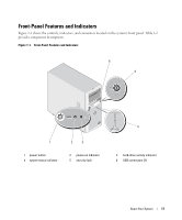
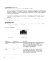
Table 1-2. Front-Panel Components Item Component Icon 1 Power button 2 Power-on indicator 3 Hard-drive activity indicator 4 System status indicator 5 Security lock 6 USB connectors Description The power button turns system power off and on. NOTICE: If you turn off the system using the power button and the system is running an ACPI-compliant operating system, the system can perform an orderly shutdown before power is turned off. If the power button is pressed for more than 4 seconds, the system power will turn off regardless of the current operating system state. If the system is not running an ACPI-compliant operating system, power is turned off immediately after the power button is pressed. The power button is enabled in the System Setup program. When disabled, the button can only turn the system power on. For more information, see "Using the System Setup Program" on page 29 and the operating system's documentation. On: System power is on. Blinking: System is on but in standby state, or system is off but still connected to the power source. Flashes when data is being read from or written to the internal SATA hard drives that are connected to the integrated controller. Blue: Normal system operation. Amber: Flashes when the system needs attention due to a problem with power supplies, fans, system temperature, or hot-plug hard drives. NOTE: If the system is connected to AC power and an error has been detected, the amber system status indicator flashes regardless of whether the system has been powered on. Controls access to the system's internal components. Connects USB 2.0-compliant devices to the system. 12 About Your System
-
 1
1 -
2
-
3
-
4
-
5
-
6
-
 7
7 -
 8
8 -
 9
9 -
 10
10 -
 11
11 -
 12
12 -
 13
13 -
 14
14 -
 15
15 -
 16
16 -
 17
17 -
18
-
19
-
20
-
21
-
22
-
23
-
24
-
25
-
26
-
27
-
28
-
29
-
30
-
31
-
32
-
33
-
34
-
35
-
36
-
37
-
38
-
39
-
40
-
41
-
42
-
43
-
44
-
45
-
46
-
47
-
48
-
49
-
50
-
51
-
52
-
53
-
54
-
55
-
56
-
57
-
58
-
59
-
60
-
61
-
62
-
63
-
64
-
65
-
66
-
67
-
68
-
69
-
70
-
71
-
72
-
73
-
74
-
75
-
76
-
77
-
78
-
79
-
80
-
81
-
82
-
83
-
84
-
85
-
86
-
87
-
88
-
89
-
90
-
91
-
92
-
93
-
94
-
95
-
96
-
97
-
98
-
99
-
100
-
101
-
102
-
103
-
104
-
105
-
106
-
107
-
108
-
109
-
110
-
111
-
112
-
113
-
114
-
115
-
116
-
117
-
118
-
119
-
120
-
121
-
122
-
123
-
124
-
125
-
126
-
127
-
128
-
129
-
130
-
131
-
132
-
133
-
134
-
135
-
136
-
137
-
138
-
139
-
140
-
141
-
142
-
143
-
144
-
145
-
146
-
147
-
148
-
149
-
150
-
151
-
152
-
153
-
154
-
155
-
156
-
157
-
158
 |
 |
