Dell XPS 600 Renegade Owner's Manual - Page 119
the CPU FAN1 and CPU FAN2 connectors, on the system board.
 |
View all Dell XPS 600 Renegade manuals
Add to My Manuals
Save this manual to your list of manuals |
Page 119 highlights
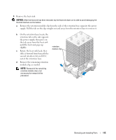
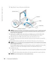
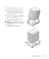
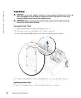
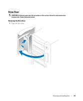
9 Reinstall the second retention module clip. 10 Lower the airflow shroud over the heat sink. 11 Reconnect the two cooling fan power cables to the CPU FAN1 and CPU FAN2 connectors (see "System Board Components" on page 78) on the system board. 12 Reconnect the power cable to the POWER12V connector (see "System Board Components" on page 78) on the system board. 13 Close the computer cover (see "Closing the Computer Cover" on page 125). NOTICE: To connect a network cable, first plug the cable into the network port or device and then plug it into the computer. 14 Connect your computer and devices to electrical outlets, and turn them on. Removing and Installing Parts 119
-
 1
1 -
2
-
3
-
4
-
5
-
6
-
7
-
8
-
9
-
10
-
11
-
12
-
13
-
14
-
15
-
16
-
17
-
18
-
19
-
20
-
21
-
22
-
23
-
24
-
25
-
26
-
27
-
28
-
29
-
30
-
31
-
32
-
33
-
34
-
35
-
36
-
37
-
38
-
39
-
40
-
41
-
42
-
43
-
44
-
45
-
46
-
47
-
48
-
49
-
50
-
51
-
52
-
53
-
54
-
55
-
56
-
57
-
58
-
59
-
60
-
61
-
62
-
63
-
64
-
65
-
66
-
67
-
68
-
69
-
70
-
71
-
72
-
73
-
74
-
75
-
76
-
77
-
78
-
79
-
80
-
81
-
82
-
83
-
84
-
85
-
86
-
87
-
88
-
89
-
90
-
91
-
92
-
93
-
94
-
95
-
96
-
97
-
98
-
99
-
100
-
101
-
102
-
103
-
104
-
105
-
106
-
107
-
108
-
109
-
110
-
111
-
112
-
113
-
 114
114 -
 115
115 -
 116
116 -
 117
117 -
 118
118 -
 119
119 -
 120
120 -
 121
121 -
 122
122 -
 123
123 -
 124
124 -
125
-
126
-
127
-
128
-
129
-
130
-
131
-
132
-
133
-
134
-
135
-
136
-
137
-
138
-
139
-
140
-
141
-
142
-
143
-
144
-
145
-
146
-
147
-
148
-
149
-
150
-
151
-
152
-
153
-
154
-
155
-
156
-
157
-
158
-
159
-
160
-
161
-
162
-
163
-
164
-
165
-
166
 |
 |
Removing and Installing Parts
119
9
Reinstall the second retention module clip.
10
Lower the airflow shroud over the heat sink.
11
Reconnect the two cooling fan power cables to
the CPU FAN1 and CPU FAN2 connectors
(see "System Board Components" on page 78)
on the system board.
12
Reconnect the power cable to the POWER12V
connector (see "System Board Components" on
page 78) on the system board.
13
Close the computer cover (see "Closing the
Computer Cover" on page 125).
NOTICE:
To connect a network cable, first plug the
cable into the network port or device and then plug it
into the computer.
14
Connect your computer and devices to
electrical outlets, and turn them on.