Dell XPS M1210 Owner's Manual - Page 115
Optical Drive, Turn the computer upside-down.
 |
View all Dell XPS M1210 manuals
Add to My Manuals
Save this manual to your list of manuals |
Page 115 highlights
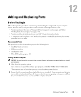
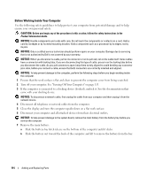
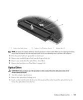
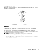
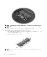
1 2 3 1 battery-bay latch release 2 battery (9-cell battery shown) 3 battery tabs (2) NOTE: To replace the battery, follow the removal procedure in reverse order. When you are replacing the battery, ensure that you properly insert the two battery tabs into the corresponding slots in the base of the computer. 8 Press the power button to ground the system board. 9 Remove any installed ExpressCard from the ExpressCard slot. 10 Remove any media from the optical drive, if installed. 11 Remove the hard drive (see "Hard Drive" on page 116). Optical Drive CAUTION: Before you begin any of the procedures in this section, follow the safety instructions in the Product Information Guide. 1 Turn the computer upside-down. 2 Remove the optical-drive locking screw. 3 Insert a scribe into the notch by the screw hole and push the scribe toward the optical drive bay to release the optical drive from the bay. Adding and Replacing Parts 115
-
 1
1 -
2
-
3
-
4
-
5
-
6
-
7
-
8
-
9
-
10
-
11
-
12
-
13
-
14
-
15
-
16
-
17
-
18
-
19
-
20
-
21
-
22
-
23
-
24
-
25
-
26
-
27
-
28
-
29
-
30
-
31
-
32
-
33
-
34
-
35
-
36
-
37
-
38
-
39
-
40
-
41
-
42
-
43
-
44
-
45
-
46
-
47
-
48
-
49
-
50
-
51
-
52
-
53
-
54
-
55
-
56
-
57
-
58
-
59
-
60
-
61
-
62
-
63
-
64
-
65
-
66
-
67
-
68
-
69
-
70
-
71
-
72
-
73
-
74
-
75
-
76
-
77
-
78
-
79
-
80
-
81
-
82
-
83
-
84
-
85
-
86
-
87
-
88
-
89
-
90
-
91
-
92
-
93
-
94
-
95
-
96
-
97
-
98
-
99
-
100
-
101
-
102
-
103
-
104
-
105
-
106
-
107
-
108
-
109
-
 110
110 -
 111
111 -
 112
112 -
 113
113 -
 114
114 -
 115
115 -
 116
116 -
 117
117 -
 118
118 -
 119
119 -
 120
120 -
121
-
122
-
123
-
124
-
125
-
126
-
127
-
128
-
129
-
130
-
131
-
132
-
133
-
134
-
135
-
136
-
137
-
138
-
139
-
140
-
141
-
142
-
143
-
144
-
145
-
146
-
147
-
148
-
149
-
150
-
151
-
152
-
153
-
154
-
155
-
156
-
157
-
158
-
159
-
160
-
161
-
162
-
163
-
164
-
165
-
166
-
167
-
168
-
169
-
170
-
171
-
172
-
173
-
174
-
175
-
176
-
177
-
178
-
179
-
180
-
181
-
182
-
183
-
184
-
185
-
186
-
187
-
188
-
189
-
190
-
191
-
192
 |
 |
