HP 6125G HP 6125G & 6125G/XG Blade Switches ACL and QoS Configuration - Page 61
Local precedence re-marking configuration example, Network requirements
 |
View all HP 6125G manuals
Add to My Manuals
Save this manual to your list of manuals |
Page 61 highlights
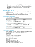
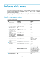
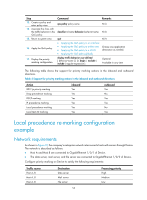
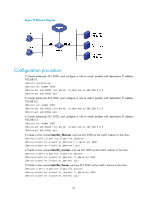
Step 13. Create a policy and enter policy view. 14. Associate the class with the traffic behavior in the QoS policy. 15. Return to system view. 16. Apply the QoS policy. 17. Display the priority marking configuration. Command qos policy policy-name classifier tcl-name behavior behavior-name quit • Applying the QoS policy to an interface • Applying the QoS policy to online users • Applying the QoS policy to a VLAN • Applying the QoS policy globally display traffic behavior user-defined [ behavior-name ] [ | { begin | exclude | include } regular-expression ] Remarks N/A N/A N/A Choose one application destination as needed. Optional. Available in any view The following table shows the support for priority marking actions in the inbound and outbound directions. Table 4 Support for priority marking actions in the inbound and outbound directions Action 802.1p priority marking Drop precedence marking DSCP marking IP precedence marking Local precedence marking Local QoS ID marking inbound Yes Yes Yes Yes Yes Yes outbound Yes No Yes Yes No Yes Local precedence re-marking configuration example Network requirements As shown in Figure 19, the company's enterprise network interconnects hosts with servers through Device. The network is described as follows: • Host A and Host B are connected to GigabitEthernet 1/0/1 of Device. • The data server, mail server, and file server are connected to GigabitEthernet 1/0/2 of Device. Configure priority marking on Device to satisfy the following requirements: Traffic source Host A, B Host A, B Host A, B Destination Data server Mail server File server Processing priority High Medium Low 55
-
 1
1 -
2
-
3
-
4
-
5
-
6
-
7
-
8
-
9
-
10
-
11
-
12
-
13
-
14
-
15
-
16
-
17
-
18
-
19
-
20
-
21
-
22
-
23
-
24
-
25
-
26
-
27
-
28
-
29
-
30
-
31
-
32
-
33
-
34
-
35
-
36
-
37
-
38
-
39
-
40
-
41
-
42
-
43
-
44
-
45
-
46
-
47
-
48
-
49
-
50
-
51
-
52
-
53
-
54
-
55
-
 56
56 -
 57
57 -
 58
58 -
 59
59 -
 60
60 -
 61
61 -
 62
62 -
 63
63 -
 64
64 -
 65
65 -
 66
66 -
67
-
68
-
69
-
70
-
71
-
72
-
73
-
74
-
75
-
76
-
77
-
78
-
79
-
80
-
81
-
82
-
83
-
84
 |
 |
