HP 6125G HP 6125G & 6125G/XG Blade Switches ACL and QoS Configuration - Page 66
Redirect-to-next hop configuration example, Network requirements, Configuration procedure
 |
View all HP 6125G manuals
Add to My Manuals
Save this manual to your list of manuals |
Page 66 highlights
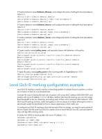
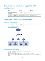
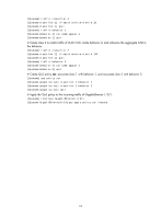
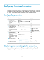
Step 9. Associate the class with the traffic behavior in the QoS policy. 10. Return to system view. 11. Apply the QoS policy. Command classifier tcl-name behavior behavior-name quit • Applying the QoS policy to an interface • Applying the QoS policy to a VLAN • Applying the QoS policy globally Remarks N/A N/A Choose one application destination as needed. Redirect-to-next hop configuration example Network requirements As shown in Figure 20, the network is described as follows: • Device A is connected to Device through two links. At the same time, Device A and Device B are each connected to other devices. • GigabitEthernet 1/0/2 of Device A and GigabitEthernet 1/0/2 of Device B belong to VLAN 200. • Ethernet 1/3 of Device A and Ethernet 1/3 of Device B belong to VLAN 201. • On Device A, the IP address of VLAN-interface 200 is 200.1.1.1/24, and that of VLAN-interface 201 is 201.1.1.1/24. • On Device B, the IP address of VLAN-interface 200 is 200.1.1.2/24, and that of VLAN-interface 201 is 201.1.1.2/24. Configure the actions of redirecting traffic to the next hop to implement policy-based routing and satisfy the following requirements: • Packets with source IP address 2.1.1.1 received on GigabitEthernet 1/0/1 of Device A are forwarded to IP address 200.1.1.2. • Packets with source IP address 2.1.1.2 received on GigabitEthernet 1/0/1 of Device A are forwarded to IP address 201.1.1.2. • Other packets received on GigabitEthernet 1/0/1 of Device A are forwarded according to the routing table. Figure 20 Network diagram Configuration procedure # Create basic ACL 2000, and configure a rule to match packets with source IP address 2.1.1.1. system-view [DeviceA] acl number 2000 60
-
 1
1 -
2
-
3
-
4
-
5
-
6
-
7
-
8
-
9
-
10
-
11
-
12
-
13
-
14
-
15
-
16
-
17
-
18
-
19
-
20
-
21
-
22
-
23
-
24
-
25
-
26
-
27
-
28
-
29
-
30
-
31
-
32
-
33
-
34
-
35
-
36
-
37
-
38
-
39
-
40
-
41
-
42
-
43
-
44
-
45
-
46
-
47
-
48
-
49
-
50
-
51
-
52
-
53
-
54
-
55
-
56
-
57
-
58
-
59
-
60
-
 61
61 -
 62
62 -
 63
63 -
 64
64 -
 65
65 -
 66
66 -
 67
67 -
 68
68 -
 69
69 -
 70
70 -
 71
71 -
72
-
73
-
74
-
75
-
76
-
77
-
78
-
79
-
80
-
81
-
82
-
83
-
84
 |
 |