HP LaserJet 1100 Service Manual - Page 85
Paper exit sensor flag removal
 |
View all HP LaserJet 1100 manuals
Add to My Manuals
Save this manual to your list of manuals |
Page 85 highlights
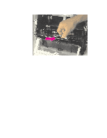
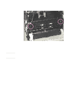
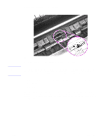
Paper exit sensor flag removal NOTE: Figure 4-26Paper Exit Sensor Flag Prior to this step: Remove the output roller and delivery assembly. Before proceeding, examine the paper exit sensor flag. It is important to note the position of the spring mechanism on the flag. The spring must be reinstalled to exactly this position, because installing it incorrectly will cause a control panel error message. 1 Remove the paper exit sensor flag by pressing down on the left side and pulling up on the right side. To reinstall Place the left side of the flag in the correct position first, then slide the right side into place, making certain the spring is on top of the flag. If the spring exerts no pressure on the flag, it may require respringing by giving the spring an extra turn before reinstalling. The flag should fit snugly in place. C4224-90962 Internal assemblies 89
-
 1
1 -
2
-
3
-
4
-
5
-
6
-
7
-
8
-
9
-
10
-
11
-
12
-
13
-
14
-
15
-
16
-
17
-
18
-
19
-
20
-
21
-
22
-
23
-
24
-
25
-
26
-
27
-
28
-
29
-
30
-
31
-
32
-
33
-
34
-
35
-
36
-
37
-
38
-
39
-
40
-
41
-
42
-
43
-
44
-
45
-
46
-
47
-
48
-
49
-
50
-
51
-
52
-
53
-
54
-
55
-
56
-
57
-
58
-
59
-
60
-
61
-
62
-
63
-
64
-
65
-
66
-
67
-
68
-
69
-
70
-
71
-
72
-
73
-
74
-
75
-
76
-
77
-
78
-
79
-
 80
80 -
 81
81 -
 82
82 -
 83
83 -
 84
84 -
 85
85 -
 86
86 -
 87
87 -
 88
88 -
 89
89 -
 90
90 -
91
-
92
-
93
-
94
-
95
-
96
-
97
-
98
-
99
-
100
-
101
-
102
-
103
-
104
-
105
-
106
-
107
-
108
-
109
-
110
-
111
-
112
-
113
-
114
-
115
-
116
-
117
-
118
-
119
-
120
-
121
-
122
-
123
-
124
-
125
-
126
-
127
-
128
-
129
-
130
-
131
-
132
-
133
-
134
-
135
-
136
-
137
-
138
-
139
-
140
-
141
-
142
-
143
-
144
-
145
-
146
-
147
-
148
-
149
-
150
-
151
-
152
-
153
-
154
-
155
-
156
-
157
-
158
-
159
-
160
-
161
-
162
-
163
-
164
-
165
-
166
-
167
-
168
-
169
-
170
-
171
-
172
-
173
-
174
-
175
-
176
-
177
-
178
-
179
-
180
-
181
-
182
-
183
-
184
-
185
-
186
-
187
-
188
-
189
-
190
-
191
 |
 |
