HP LaserJet 1100 Service Manual - Page 86
Fusing element removal
 |
View all HP LaserJet 1100 manuals
Add to My Manuals
Save this manual to your list of manuals |
Page 86 highlights
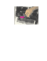
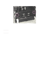
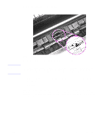
Fusing element removal NOTE: Figure 4-27Metal Clips Holding Fusing Element Prior to this step: Remove the scanner, pods, printer door, front cover, memory card (if applicable), output roller, and delivery assembly. Pay special attention to the way these metal clips are attached to the printer chassis before you remove them. This will make reassembly easier. The Fusing Element is held in place on each end by two metal spring-loaded clips. Each clip has a small black lever next to it. These levers must be in the "up" position. 1 Push each clip down and back, releasing it from the printer chassis. 90 Removal and Replacement C4224-90962
-
 1
1 -
2
-
3
-
4
-
5
-
6
-
7
-
8
-
9
-
10
-
11
-
12
-
13
-
14
-
15
-
16
-
17
-
18
-
19
-
20
-
21
-
22
-
23
-
24
-
25
-
26
-
27
-
28
-
29
-
30
-
31
-
32
-
33
-
34
-
35
-
36
-
37
-
38
-
39
-
40
-
41
-
42
-
43
-
44
-
45
-
46
-
47
-
48
-
49
-
50
-
51
-
52
-
53
-
54
-
55
-
56
-
57
-
58
-
59
-
60
-
61
-
62
-
63
-
64
-
65
-
66
-
67
-
68
-
69
-
70
-
71
-
72
-
73
-
74
-
75
-
76
-
77
-
78
-
79
-
80
-
 81
81 -
 82
82 -
 83
83 -
 84
84 -
 85
85 -
 86
86 -
 87
87 -
 88
88 -
 89
89 -
 90
90 -
 91
91 -
92
-
93
-
94
-
95
-
96
-
97
-
98
-
99
-
100
-
101
-
102
-
103
-
104
-
105
-
106
-
107
-
108
-
109
-
110
-
111
-
112
-
113
-
114
-
115
-
116
-
117
-
118
-
119
-
120
-
121
-
122
-
123
-
124
-
125
-
126
-
127
-
128
-
129
-
130
-
131
-
132
-
133
-
134
-
135
-
136
-
137
-
138
-
139
-
140
-
141
-
142
-
143
-
144
-
145
-
146
-
147
-
148
-
149
-
150
-
151
-
152
-
153
-
154
-
155
-
156
-
157
-
158
-
159
-
160
-
161
-
162
-
163
-
164
-
165
-
166
-
167
-
168
-
169
-
170
-
171
-
172
-
173
-
174
-
175
-
176
-
177
-
178
-
179
-
180
-
181
-
182
-
183
-
184
-
185
-
186
-
187
-
188
-
189
-
190
-
191
 |
 |

90
Removal and Replacement
C4224-90962
Fusing element removal
Figure 4-27
Metal Clips Holding Fusing Element
Prior to this step: Remove the scanner, pods, printer door, front cover, memory card (if
applicable), output roller, and delivery assembly.
NOTE:
Pay special attention to the way these metal clips are attached to the printer chassis before
you remove them. This will make reassembly easier.
The Fusing Element is held in place on each end by two metal spring-loaded clips. Each clip
has a small black lever next to it. These levers must be in the “up” position.
1
Push each clip down and back, releasing it from the printer chassis.