HP Surestore Tape Library Model 2/28 HP DLT Tape Library 28/48-Slot - User& - Page 18
Library Features, Location of Library Features
 |
View all HP Surestore Tape Library Model 2/28 manuals
Add to My Manuals
Save this manual to your list of manuals |
Page 18 highlights
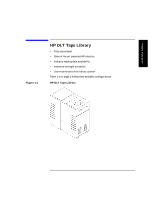
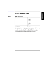
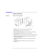
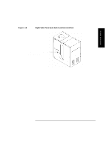
Product Description Library Features Figure 1-2 Library Features Location of Library Features Front Panel Back Panel 1. Mailslot is used to load and unload single tape cartridges. 2. Power switch turns power to the unit on and off. 3. Front and back lower panels cover the front and back of the library. 4. Power connector connects the power cord to the library. 5. SCSI ports allow connection of the library to the host using SCSI cables. 6. SCSI interface mode switches specify termination and term power settings for each SCSI bus. 7. SCSI bus indicators indicate SCSI bus status. Each SCSI bus has an indicator. 8. Control panel displays messages and allows selection of library operations. 1-6
-
 1
1 -
2
-
3
-
4
-
5
-
6
-
7
-
8
-
9
-
10
-
11
-
12
-
 13
13 -
 14
14 -
 15
15 -
 16
16 -
 17
17 -
 18
18 -
 19
19 -
 20
20 -
 21
21 -
 22
22 -
 23
23 -
24
-
25
-
26
-
27
-
28
-
29
-
30
-
31
-
32
-
33
-
34
-
35
-
36
-
37
-
38
-
39
-
40
-
41
-
42
-
43
-
44
-
45
-
46
-
47
-
48
-
49
-
50
-
51
-
52
-
53
-
54
-
55
-
56
-
57
-
58
-
59
-
60
-
61
-
62
-
63
-
64
-
65
-
66
-
67
-
68
-
69
-
70
-
71
-
72
-
73
-
74
-
75
-
76
-
77
-
78
-
79
-
80
-
81
-
82
-
83
-
84
-
85
-
86
-
87
-
88
-
89
-
90
-
91
-
92
-
93
-
94
-
95
-
96
-
97
-
98
-
99
-
100
-
101
-
102
-
103
-
104
-
105
-
106
-
107
-
108
-
109
-
110
 |
 |

1-6
Product Description
Library Features
Library Features
Figure 1-2
Location of Library Features
1.
Mailslot
is used to load and unload single tape cartridges.
2.
Power switch
turns power to the unit on and off.
3.
Front and back lower panels
cover the front and back of the library.
4.
Power connector
connects the power cord to the library.
5.
SCSI ports
allow connection of the library to the host using SCSI cables.
6.
SCSI interface mode switches
specify termination and term power
settings for each SCSI bus.
7.
SCSI bus indicators
indicate SCSI bus status. Each SCSI bus has an
indicator.
8.
Control panel
displays messages and allows selection of library
operations.
Front Panel
Back Panel