Icom IC-M804 Instruction Manual - Page 11
Function display (Main screen), Status area, Task area, Information area, Channel area
 |
View all Icom IC-M804 manuals
Add to My Manuals
Save this manual to your list of manuals |
Page 11 highlights
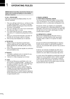
PANEL DESCRIPTION 2 ■ Function display (Main screen) D Information area Status area Task area Information area The 9 digit MMSI (Maritime Mobile Service Identity: DSC self ID) code and the following indicators are displayed in the information area. 2 Indicator Description Displayed when receiving a signal or when the squelch is open. Displayed while transmitting. Position data Software Key area Channel area and Time area D Status area The current status is displayed in the Status area. Indicator Description SQL Displayed when the Squelch function is ON. NB Displayed when the Noise Blanker function is ON. Displayed when the AGC function is OFF. NR Displayed when the Noise Reduction function is ON. • Displayed when the GPS receiver is activated and valid position data is received. • Blinks while invalid position data is being received. • Displayed when there is an unread DSC message. • Blinks when there is a new DSC message. Displayed when the "CH Auto Switch" in the DSC settings is set to an option except "Accept after 10 sec." Displayed when the internal speaker is OFF. D Channel area The selected operating channel number, channel name, and the following indicators are displayed in the Channel area. Tune Scan • Displayed when the received audio is recorded. (p. 12) • Displayed when recording the received audio is stopped. (p. 12) Displayed when the Tune function is ON. Displayed during a scan. • Displayed when the volume is set to between 1 to 20. Indicator Description Displayed when the Channel Select mode is selected. Displayed when the Group Select mode is selected. Displayed when the Clarity function is ON. The number is the added to (+) or subtracted from (−) the frequency. • Displayed when the volume is set to 0. D Task area Displayed when the Emergency FREQ channel is selected. When receiving, the S meter displays the relative signal strength. The current mode is displayed in the Task area. Indicator Description When transmitting, the Current meter displays the output power level. STBY RT DSC Displayed while in the Standby mode. Displayed while in the Radio Telephone (RT) mode. L Returns to the Standby mode if no operation occurs during the preset period of time. Displayed after making or receiving a DSC call. SIMP Displayed when a Simplex channel is selected. DUP Displayed when a Duplex channel is selected. J3E/H3E/ LSB/J2B/ Displays the selected operating mode. F1B/A1A 6
-
 1
1 -
2
-
3
-
4
-
5
-
 6
6 -
 7
7 -
 8
8 -
 9
9 -
 10
10 -
 11
11 -
 12
12 -
 13
13 -
 14
14 -
 15
15 -
 16
16 -
17
-
18
-
19
-
20
-
21
-
22
-
23
-
24
-
25
-
26
-
27
-
28
-
29
-
30
-
31
-
32
-
33
-
34
-
35
-
36
-
37
-
38
-
39
-
40
-
41
-
42
-
43
-
44
-
45
-
46
-
47
-
48
-
49
-
50
-
51
-
52
-
53
-
54
-
55
-
56
-
57
-
58
-
59
-
60
-
61
-
62
-
63
-
64
-
65
-
66
-
67
-
68
-
69
-
70
-
71
-
72
-
73
-
74
-
75
-
76
-
77
-
78
-
79
-
80
-
81
-
82
-
83
-
84
-
85
-
86
-
87
-
88
 |
 |
