Icom IC-R20 Instruction Manual
Icom IC-R20 Manual
 |
View all Icom IC-R20 manuals
Add to My Manuals
Save this manual to your list of manuals |
Icom IC-R20 manual content summary:
- Icom IC-R20 | Instruction Manual - Page 1
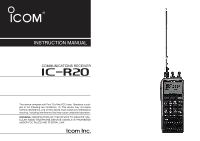
INSTRUCTION MANUAL COMMUNICATIONS RECEIVER iR20 This device complies with Part 15 of the FCC rules. Operation is subject to the following two conditions: (1) This device may not cause harmful interference, and (2) this device must accept any interference received, including interference that may - Icom IC-R20 | Instruction Manual - Page 2
FOREWORD Thank you for purchasing this Icom product. The IC-R20 COMMUNICATIONS RECEIVER is designed and built with Icom's superior technology and craftsmanship. With proper care, this product should provide you with years of trouble-free operation. We want to take a couple of moments of your time to - Icom IC-R20 | Instruction Manual - Page 3
battery pack or batteries will become exhausted, and will need to be recharged. RESPECT other people's privacy. Information overheard but not intended for you cannot lawfully be used in any way. For U.S.A. only CAUTION: Changes or modifications to this device, not expressly approved by Icom - Icom IC-R20 | Instruction Manual - Page 4
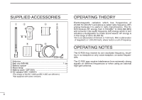
SUPPLIED ACCESSORIES q w e r t y q Antenna 1 w Belt clip (MB-98 1 set e Battery spacer 1 r Hand strap 1 t Battery pack* (BP-206 1 yAC adaptor*(BC-149A/D 1 (The shape of the BC-149A and BC-149D are different.) *Not supplied with some versions. OPERATING THEORY - Icom IC-R20 | Instruction Manual - Page 5
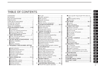
/CHARGING ... 8-10 ■ Battery installation 8 ■ Caution 9 ■ General description 26 ■ Memory channel programming 26 ■ IC recorder 64 9 ■ Partial reset 67 ■ Memory bank setting 27 ■ All reset 68 10 ■ Memory bank selection 28 12 CONTROL COMMAND 68-69 ■ Programming memory/bank name - Icom IC-R20 | Instruction Manual - Page 6
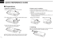
from the receiver. w Remove the supplied battery spacer for R6 (AA) size bat- tery use. e Install the Li-Ion battery pack (BP-206). • Be sure to observe the correct direction. • Charge Li-Ion battery pack (BP-206) before use. (Refer to p. IV for charging instructions.) •Battery pack installation - Icom IC-R20 | Instruction Manual - Page 7
REFERENCE GUIDE D Belt clip Conveniently attaches to your belt. Attach the belt clip with the supplied screws using a phillips screwdriver. w Clip the belt clip to your belt. D Swivel belt clip (Option) The optional swivel belt clip (MB-86) is useful for easy attaching/detaching the receiver to - Icom IC-R20 | Instruction Manual - Page 8
GUIDE To remove: r Turn the receiver upside down, and then lift to release the receiver from the belt clip as shown at upper right. D Antenna Insert the supplied antenna into the antenna connector and screw down the antenna as shown at right. NEVER hold the antenna when carrying the receiver - Icom IC-R20 | Instruction Manual - Page 9
pack (BP-206). w Plug the AC adaptor into an AC outlet. eTurn OFF the receiver, then insert the adaptor plug into the [DC] jack of the receiver. RWARNING!: NEVER attempt to charge any other batteries. Because the IC-R20 can charge the BP-206 only. Keep the jack cover attached when jack is not in - Icom IC-R20 | Instruction Manual - Page 10
QUICK REFERENCE GUIDE D Basic operation 1. Turning ON the receiver ➥ Push [POWER] for 1 sec. to turn the power dial will allow you to dial in the frequency you want to operate. Pages 9 and 15 will instruct you on how to set the tuning speed. [Using the tuning dial] qPush [BAND] several times - Icom IC-R20 | Instruction Manual - Page 11
QUICK REFERENCE GUIDE Quick reference guide [Using the keypad] ➥ Enter receive mode. • FM, WFM, AM, LSB, USB and CW are available. DUALWATCH MAIN/SUB POWER BAND VFO MHz MODE SCAN MR S.MW 1 2 3 SCOPE 4 5 6 0 AFC 7 8 9 LOCK REC MODE SCAN Front ■ Memory programming The IC-R20 - Icom IC-R20 | Instruction Manual - Page 12
scan, different frequencies must be programmed into "A" and "B" channels. D Programming scan edges A start frequency must be programmed into a "xxA," and end frequency must be programmed into a "xxB" memory channel. 1. Setting frequency In VFO mode, set the desired receive frequency mode. • When - Icom IC-R20 | Instruction Manual - Page 13
LOCK REC MODE SCAN Front • Full scan √ SCAN:ALL PSKIP • Band scan √ SCAN:BAND PSKIP • Programmed scan PSKIP √ SCAN:PROG-01 Selectable between "00" to "24" if programmed Quick reference guide 3. Starting scan Release [MODE SCAN] to start the scan. • Rotate [R-DIAL] to change the scanning - Icom IC-R20 | Instruction Manual - Page 14
to quickly and easily transfer the programmed contents between the IC-R20 and the connected PC. t EXTERNAL DC-IN CONNECTOR [DC] (p. 9) Connects an AC adaptor or an optional cigarette lighter cable for both charging the installed re-chargeable battery pack and operating. y EXTERNAL SPEAKER CONNECTOR - Icom IC-R20 | Instruction Manual - Page 15
GAIN MODE SCAN CENTER MR S.MW 3 SCOPE M.N 6 0 AFC TS 9 LOCK IC Recorder REC qDUALWATCH/CLEAR KEY [DUALWATCH] 1 DUALWATCH ➥ Push for 1 sec. to - quency. e POWER KEY [POWER] Push for 1 sec. to turn the receiver power ON POWER and OFF. r BAND KEY [BAND] Push to select the operating frequency - Icom IC-R20 | Instruction Manual - Page 16
USB, LSB, CW). (p. 16) ➥ Push for 1 sec. to start a scan. (p. 35) u MEMORY KEY [MR S.MW] ➥ Push to select between memory mode, TV MR S.MW channel and PreSet channel. (p. 11 for 1 sec. to trade the volume control ([L-DIAL], [Y]/[Z]) and tuning control ([RDIAL]) functions. (p. 23 appears when - Icom IC-R20 | Instruction Manual - Page 17
Non-skip channel - no skip indicator appears. ➥ Push for 1 sec. to program a paused fre- quency as a skip frequency while scanning. (p. 39) !4 MEMORY selection, etc. ➥ Push for 1 sec. to turn the AFC (Automatic Frequency Control) function ON and OFF. (p. 21) !6 TONE SQUELCH KEY [7 TONE] TONE - Icom IC-R20 | Instruction Manual - Page 18
1 PANEL DESCRIPTION !8 TUNING STEP KEY [9 TS] TS ➥ Inputs digit '9' for frequency input, memory channel selection, etc. ➥ Push for 1 sec. to select the tuning step. (p. 14) !9 LOCK KEY [• LOCK] ➥ Inputs MHz digit for frequency input. (p. 15) LOCK ➥ Push for 1 sec. to toggle the lock - Icom IC-R20 | Instruction Manual - Page 19
source. ➥" " appears when the batteries are nearing ex- haustion. • IC-R20 installed the BP-206 must be charged presently, but when it installed alkaline batteries can be operate for a while. is in use. (p. 45) ➥ "VSC" appears while the VSC (Voice Squelch Control) function is in use. (p. 45) 6 - Icom IC-R20 | Instruction Manual - Page 20
name is programmed. !4 FREQUENCY READOUT Shows an operating frequency. • The smaller readout appears at right when tuning step is selected 0.1 kHz or 0.01 kHz steps. • The decimal point blinks during scan. !5 RECEIVE MODE INDICATOR (p. 16) Shows the selected receive mode. • FM, WFM AM, LSB, USB and - Icom IC-R20 | Instruction Manual - Page 21
before installing or replacing the batteries. qRemove the battery cover from the receiver. wFor alkaline battery use, attach the supplied battery spacer. w e q 1 D Battery pack installation 2 q Remove the battery cover from the receiver. w Remove the supplied battery spacer for R6 (AA) size bat - Icom IC-R20 | Instruction Manual - Page 22
Insert the battery pack (BP-206) into the receiver. (p. 8) wPlug the AC adaptor (BC-149A/D*) into an AC outlet; or the optional CP-18A/E into a cigarette lighter socket. * Not supplied with some versions. eTurn OFF the receiver, then insert the adaptor plug into [DC] of the receiver. IC-R20 to [DC - Icom IC-R20 | Instruction Manual - Page 23
periods is recommended. BC-156 CAUTION: Shorten or remove the telescoping antenna before charging to prevent the receiver from overturning. If the charge indicator flashes orange, there may be a problem with the battery pack (or charger). Reinsert the battery pack or contact your dealer. 10 - Icom IC-R20 | Instruction Manual - Page 24
0 AFC TS 9 LOCK IC Recorder REC VFO MHz receiving are generated and controlled by the VFO. D Memory mode/PreSet*/TV*/Weather† channels Memory mode is used for operation of memory channels which have programmed programmed via the optional CS-R20 programming TS 9 LOCK IC Recorder REC MR - Icom IC-R20 | Instruction Manual - Page 25
indication (USA version only) -DUP TSQL MODE FM ANL 1 AFC PSKIP √ WX PreSet channel number appears. "WX" indication appears. ■ Operating band selection The receiver can receive the AM broadcast, HF bands, 50 MHz, FM broadcast, VHF air, 144 MHz, 300 MHz, 400 MHz, 800 MHz,* 1200 MHz or 2400 - Icom IC-R20 | Instruction Manual - Page 26
3 FREQUENCY AND CHANNEL SETTING • Available frequency bands MODE AM 1620 AM broadcast band MODE AM 5000 HF band MODE FM 51000 50 MHz band MODE FM 2425000 2400 MHz band : Push BAND : Rotating while pushing BAND Initial frequencies shown will differ according to version. MODE FM 1295000 1200 - Icom IC-R20 | Instruction Manual - Page 27
appear when setting the tuning step for the VHF air band and AM broadcast band, respectively. The following tuning steps are available for the IC-R20. • 0.01 kHz • 0.1 kHz • 1.0 kHz • 5.0 kHz • 6.25 kHz • 8.33 kHz* • 9.0 kHz* • 10.0 kHz • 12.5 kHz • 15.0 kHz • 20.0 kHz • 25.0 kHz • 30.0 kHz • 50 - Icom IC-R20 | Instruction Manual - Page 28
3 FREQUENCY AND CHANNEL SETTING D Using the keypad The frequency can be directly set via numeral keys. • When editing a frequency outside of the frequency range, the previously displayed frequency is automatically recalled after editing last digit. qPush [VFO MHz] to select VFO mode, if necessary. - Icom IC-R20 | Instruction Manual - Page 29
modes are determined by the physical properties of the radio signals. The receiver has 6 receive modes: FM, WFM, AM, LSB, USB and CW modes. The mode selection is stored independently in each band and memory channels. Typically, AM mode is used for the AM broadcast stations (0. - Icom IC-R20 | Instruction Manual - Page 30
4 BASIC OPERATION ■ Receiving Make sure charged battery pack (BP-206) or brand new alkaline batteries are installed (p. 8). q Push [POWER] for 1 count system. • Push and hold [SQL] to open the squelch manually. tWhen a signal is received: • Squelch opens and audio is emitted. • The S-meter shows - Icom IC-R20 | Instruction Manual - Page 31
level setting The squelch circuit mutes the received audio signal depending on the signal strength. The receiver has 9 squelch levels, a continuously to weak signals without disturbing the squelch setting or to open the squelch manually even when mute functions such as the tone squelch are in use. 4 - Icom IC-R20 | Instruction Manual - Page 32
8 RF GAIN MODE SCAN CENTER MR S.MW 3 SCOPE M.N 6 0 AFC TS 9 LOCK IC Recorder REC -DUP TSQL AFC MODE FM ANL 146 010 √ ATT ATT PSKIP "ATT" appears while the attenuator functions is in use. ■ RF gain The receiver gain can be reduced with the RF gain setting. This may help - Icom IC-R20 | Instruction Manual - Page 33
through a repeater, some utility communications, etc. During duplex operation, the transmit station frequency is shifted from the receive station frequency by the offset frequency. Repeater information (offset frequency and shift direction) can be programmed into memory channels. (p. 26 - Icom IC-R20 | Instruction Manual - Page 34
Control) function tunes the displayed frequency automatically when an off-center frequency is received SCOPE M.N 6 0 AFC TS 9 LOCK IC Recorder REC 0 AFC "AFC" appears while when an off-frequency is received. NOTE: The AFC noise when USB, LSB or . -DUP TSQL MODE USB NB AFC 145100 PSKIP - Icom IC-R20 | Instruction Manual - Page 35
BASIC OPERATION 4 ■ Band scope The band scope function allows you to visually check a specified frequency range. Sweep range can be selected from ±14 kHz through ±1400 kHz. q Set the desired frequency as band scope center frequency. w While pushing and holding [2 SWEEP], rotate [R-DIAL] to select - Icom IC-R20 | Instruction Manual - Page 36
4 BASIC OPERATION ■ [DIAL] function assignment The frequency control dial can be traded with an audio volume control dial or [Y]/[Z] keys to suit your preference. ➥ Push [1 DIAL.SEL] for 1 sec. to toggle the dial function from tuning dial and audio volume. [R-DIAL] [L-DIAL] - - Icom IC-R20 | Instruction Manual - Page 37
5 DUALWATCH OPERATION ■ Main band selection ➥ Push [MAIN/SUB] momentarily to select the upper band or lower band as main band (operating band) alternately. -DUP TSQL PS 145 25000 PRIO 000 FM AFC -DUP TSQL PS 438 00000 PRIO 000 FM ■ Band exchange ➥ Push [MAIN/SUB] for 1 sec to exchange - Icom IC-R20 | Instruction Manual - Page 38
5 DUALWATCH OPERATION ■ Setting audio volume qPush [DUALWATCH] for 1 sec. to enter the dualwatch operation, if necessary wPush and hold [SQL], push [Y] or [Z] to adjust the audio level for the main band. • Pushing and holding either key changes the audio level continuously. • The display shows the - Icom IC-R20 | Instruction Manual - Page 39
, etc. Up to 100 channels can be assigned into a bank. D Memory channel contents The following information can be programmed into memory channels: • Operating frequency (p. 14) • Receive mode (p. 16) • Duplex direction (+DUP or -DUP) with an offset fre- quency (p. 20) • Tone squelch or DTCS squelch - Icom IC-R20 | Instruction Manual - Page 40
6 MEMORY CHANNELS ■ Memory bank setting The IC-R20 has a total of 26 banks (A to Z). Regular memory channels, 000 to 999, are assigned into the desired bank for easy memory management. qPush [MR S.MW] - Icom IC-R20 | Instruction Manual - Page 41
pushing [BAND], rotate [R-DIAL] to select the de- sired bank (A to Z). • The bank can also be selected by pushing [BAND] several times. • Only programmed banks are displayed. [R-DIAL] -DUP TSQL AFC MODE FM ANL 145 870 √ ATT PSKIP µ 001 Rotate [R-DIAL] while BAND pushing [BAND] MR S.MW - Icom IC-R20 | Instruction Manual - Page 42
the select memory write condition. • 1 short and 1 long beep sound. • "µ " indicator blinks. FM 145..700µ 012 >BANK-:C-11 rWhile pushing [8 SET], rotate [R-DIAL] to select "BNAME" or "MNAME" when programming the memory name or the bank name, respectively. • The item can also be selected by pushing - Icom IC-R20 | Instruction Manual - Page 43
700 6 B:GROUP1 PSKIP √ µ 012 ATT -DUP TSQL AFC MODE FM ANL 145 700 M.N 6 M:Ricky PSKIP √ µ 012 When no memory or bank name is programmed with the selected memory channel, no indication is displayed. -DUP TSQL AFC MODE FM ANL 145 700 B:GROUP1 PSKIP √ µ 012 q Push [MR S.MW] to - Icom IC-R20 | Instruction Manual - Page 44
6 MEMORY CHANNELS ■ Copying memory contents This function transfers a memory channel's contents to VFO (or another memory channel). This is useful when searching for signals around a memory channel frequency and for recalling the offset frequency, subaudible tone frequency etc. Pushing [MR S.MW] - Icom IC-R20 | Instruction Manual - Page 45
MEMORY CHANNELS 6 ■ Memory clearing Contents of programmed memories can be cleared (blanked), if desired. qPush [MR S.MW] for 1 sec. to select the select memory write condition. • 1 short and 1 long beeps sound. • "µ " indicator - Icom IC-R20 | Instruction Manual - Page 46
be cleared or reassigned to another memory bank. INFORMATION: Even if the memory bank contents are cleared, the memory channel contents still remain programmed. qSelect the desired bank contents to be transferred or erased from the bank. ➥ Push [MR S.MW] to select memory mode. ➥ While pushing [BAND - Icom IC-R20 | Instruction Manual - Page 47
SCAN (p. 37) Band Scan edges Band edge xxA xxB edge Scan Jump Repeatedly scans between two user-programmed frequencies. Used for checking for frequencies within a specified range such as repeater output frequencies, etc. MEMORY (SKIP) SCAN Repeatedly scans memory (p. 37) channels - Icom IC-R20 | Instruction Manual - Page 48
To start the scan, release [MODE SCAN]. • Scan pauses when a signal is received. • Rotate [R-DIAL] to change the scanning direction, or resumes manually. • Push [DUALWATCH] again to stop the scan. • During full/band scan • During programmed scan -DUP TSQL AFC MODE FM ANL 148 800 PSKIP √ -DUP - Icom IC-R20 | Instruction Manual - Page 49
[MR S.MW] for 1 sec. to select select memory write condition. • 1 short and 1 long beeps sound. • "µ " indicator blinks. rRotate [R-DIAL] to select the desired programmed scan edge channel from 00A to 24A. t Push [MR S.MW] for 1 sec. • 3 beeps sound • The other scan edge channel "B," 00B to 24B - Icom IC-R20 | Instruction Manual - Page 50
PSKIP √ µ A01 SCAN:BANK-A Selectable between "A" to "Z" if programmed r Release [MODE SCAN] to start the selected scan. • Scan pauses when a signal is received. • Rotate [R-DIAL] to change the scanning direction, or resumes manually. t To stop the scan, push [DUALWATCH]. • During memory/all - Icom IC-R20 | Instruction Manual - Page 51
for band scan, "PROG-xx" for pro- grammed scan (xx= 0 to 24; programmed scan edges numbers only displayed) r Release [MODE SCAN] to start the scan. tPush scan. D During auto-memory write scanning: • When a signal is received, scan pauses and the frequency is stored into auto-memory write channel - Icom IC-R20 | Instruction Manual - Page 52
store the skip condition into the memory. • "SKIP" or "PSKIP" indicator appears, according to the skip selection in the step r. • Skip channel setting • Program skip setting -DUP TSQL AFC MODE FM ANL 145 700 B:GROUP1 PSKIP √ µ 033 ATT -DUP TSQL AFC MODE FM ANL 145 700 B:GROUP1 PSKIP - Icom IC-R20 | Instruction Manual - Page 53
from 2-20 sec. (2 sec. steps) and "HOLD," then push [8 SET]. • "2SEC"-"20SEC": Scan pauses for 2-20 sec. while receiving a signal. • "HOLD" : Scan pauses on a received a signal until it disappears. y Push [DUALWATCH] to exit set mode. SCAN OPERATION 7 IN EXPANDED SET MODE [R-DIAL] ***-SET - Icom IC-R20 | Instruction Manual - Page 54
7 SCAN OPERATION D Scan resume timer The scan restarts after the signal disappears according to the resume time. It can be set from 0-5 sec. or unlimited. q Push [8 SET] for 1 sec. to enter set mode. wRotate [R-DIAL] to select "SET EXPAND," then push [8 SET]. eRotate [R-DIAL] to turn the expand - Icom IC-R20 | Instruction Manual - Page 55
■ Priority watch types Priority watch checks for signals on the frequency every 5 sec. while operating on a VFO frequency or scanning. The receiver has 3 priority watch types to suit your needs. The watch resumes according to the selected scan resume condition. See the left page for details. NOTE: - Icom IC-R20 | Instruction Manual - Page 56
MODE FM ANL 145 870 PSKIP √ PRIO µ 001 PSKIP √ PRIO µ 001 Monitors VFO frequency for 5 sec. Pauses on a memory (bank) channel when a signal is received. • During priority watch with priority beep -DUP TSQL AFC MODE FM ANL 439 975 -DUP TSQL AFC MODE FM ANL 145 870 PSKIP √ PRIO - Icom IC-R20 | Instruction Manual - Page 57
-DUP TSQL AFC MODE FM ANL 145 870 PSKIP √ PRIO µ 001 Monitors VFO frequency Pauses on a memory for 5 sec. (bank) channel when a signal is received. • During priority watch with priority beep 8 -DUP TSQL AFC MODE FM ANL 1888 888 -DUP TSQL AFC MODE FM ANL 145 870 PSKIP √ PRIO - Icom IC-R20 | Instruction Manual - Page 58
and blinking manually. • "S" disappears and the pocket beep function is deactivated. tTo cancel the tone squelch or DTCS, rotate [R-DIAL] while pushing [7 TONE] to tone indication disappears. NOTE: The VSC (Voice Squelch Control) function opens the squelch only when receiving a modulated signal - Icom IC-R20 | Instruction Manual - Page 59
.3 192.8 210.7 241.8 74.4 88.5 103.5 123.0 146.2 165.5 179.9 196.6 218.1 250.3 77.0 91.5 107.2 127.3 151.4 167.9 183.5 199.5 225.7 254.1 NOTE: The receiver has 50 tone frequencies and consequently their spacing is narrow compared to units having 9 38 tones. Therefore, some tone frequencies may - Icom IC-R20 | Instruction Manual - Page 60
for the DTCS operation. When a different polarity is set, the DTCS never releases audio mute even when a signal with matched code number is received. q Push [8 SET] for 1 sec. to enter set mode. wRotate [R-DIAL] to select "SET EXPAND," then push [8 SET]. eRotate [R-DIAL] to turn the expanded - Icom IC-R20 | Instruction Manual - Page 61
9 COMFORTABLE RECEIVING ■ Tone scan By monitoring a signal that is being frequency or 3-digit DTCS code is matched, the squelch opens and the tone frequency or code is temporarily programmed into the selected condition, such as memory channel. • The tone scan pauses when a CTCSS tone frequency - Icom IC-R20 | Instruction Manual - Page 62
programming infrequently changed values or conditions of functions. In addition, the IC-R20 has an expanded set mode which is used for programming select "SET EXPAND." ***-SET-MODE NOISE-BLANKER -ANL -AF-FILTER -AM-ANTENNA -FM-ANTENNA >SET-EXPAND ePush [8 SET] to enter "SET EXPAND," rotate [R-DIAL - Icom IC-R20 | Instruction Manual - Page 63
PRIORITY-WATCH -KEY-TOUCH-BEEP -BEEP-LEVEL -BACKLIGHT -POWER-SAVE -NOISE-BLANKER ***-SET-MODE NOISE-BLANKER -ANL -AF-FILTER -AM-ANTENNA -FM-ANTENNA >SET-EXPAND • Priority watch (p. 51) • Key-touch beep (p. 51) • Beep output level (p. 51) • Display backlighting (p. 51) • Power save (p. 52) • Noise - Icom IC-R20 | Instruction Manual - Page 64
) must be set to ON to have a beep tone. BEEP-LEVEL BEEP-LEVEL Minimum level (no audio) Maximum level D Display backlighting The receiver has display backlighting and function key illumination with a 5 sec. timer for night time operation. The backlighting can be turned ON continuously or turned - Icom IC-R20 | Instruction Manual - Page 65
function reduces the current drain to conserve battery power. This power save function can be turned OFF, if desired. In the default setting ("AUTO" selection), the power save function is activated in 1:4 (125 msec.: 500 msec.) ratio when no signal is received for 5 sec. The ratio becomes 1:8 (125 - Icom IC-R20 | Instruction Manual - Page 66
antenna connected to the antenna connector. (default) • BAR : Use the internal bar antenna for AM broadcast band reception. AM-ANTENNA EXT -BAR AM-ANTENNA EXT >BAR External antenna Internal bar antenna D FM antenna Audio output can be adjusted Receiver power and lock function only switchable - Icom IC-R20 | Instruction Manual - Page 67
and push again to cancel it. MONITOR PUSH -HOLD MONITOR PUSH >HOLD Push to monitor Push and hold [SQL] to monitor D Auto power OFF The receiver can be set to automatically turn OFF after a specified period has past. 30 min., 1 hour, 1.5 hours, 2 hours, BUSY and OFF (default) can be speci - Icom IC-R20 | Instruction Manual - Page 68
to the scan pause time. • 2-20 : Scan pauses for 2-20 sec. on a received signal, and selected in 2 sec. steps. (default: 10 sec.) • HOLD : Scan pauses on a received signal until it disappears. Rotate [R-DIAL] to resume manually. SCAN-PAUSE 2SEC -4SEC -6SEC -8SEC >10SEC -12SEC SCAN-PAUSE 12SEC - Icom IC-R20 | Instruction Manual - Page 69
to the selected frequency band (before accessing set mode) and receiver version. The selected tuning step in VFO mode is used for . D Duplex direction Sets the duplex direction. The displaying frequency shifts the programmed offset frequency (at left below) when monitor function is in use (while - Icom IC-R20 | Instruction Manual - Page 70
10 SET MODE D Tone frequency Sets subaudible tone frequency for tone squelch operation. Total of 50 tone frequencies (67.0-254.1 Hz) are available. (default: 88.5 Hz) TONE-FREQ --88.5 TONE-FREQ 254.1 88.5 Hz setting 254.1 Hz setting • Available subaudible tone frequencies 67.0 79.7 94.8 - Icom IC-R20 | Instruction Manual - Page 71
SET MODE 10 D Memory bank link Sets the linked bank for the bank-link scan. (default: All banks are ON) qRotate [R-DIAL] to select the bank that you want to change setting. BANK-LINK BANK-A:ON -BANK-B:ON -BANK-C:ON -BANK-D:ON -BANK-E:ON -BANK-F:ON wPush [8 SET] for 1 sec. to enter the bank link - Icom IC-R20 | Instruction Manual - Page 72
-V address To distinguish equipment, each CI-V transceiver/receiver has its own Icom standard address in hexadecimal code. The ICR20's address is "6C." When 2 or more IC-R20s are connected to an optional CT-17 CI-V LEVEL CONVERTOR, set a different address for each IC- R20 in the range "01" to "7F - Icom IC-R20 | Instruction Manual - Page 73
11 OTHER FUNCTIONS ■ Antenna selection The IC-R20 has an internal bar antenna installed for receiving AM broadcast band (0.495-1.620 MHz; differ according to version) signals. In addition, the connected earphone's cable can be used as an antenna for receiving FM broadcast band (76.000-107.995 MHz; - Icom IC-R20 | Instruction Manual - Page 74
11 OTHER FUNCTIONS ■ Weather channel operation D Weather channel selection qPush [MR S.MW] "ALT" and the "WX" indications are displayed alternately and sounds a beep tone until the receiver is operated. The previously selected (used) weather channel is checked periodically during standby or while - Icom IC-R20 | Instruction Manual - Page 75
the CS-R20 CLONING SOFTWARE HELP file for details. IC-R20 • The receiver shows following indications. Write to receiver CLONE-IN CLONE During cloning Read from receiver CLONE-OUT During cloning After cloning -DUP TSQL AFC MODE FM ANL 146 010 PSKIP √ OPC-1382 to USB jack to USB port PC - Icom IC-R20 | Instruction Manual - Page 76
has occurred. In such a case, the receiver automatically performs ALL RESET while turning power OFF and ON. CLONE-ERROR Turn power OFF, then ON ALL-RESET -DUP TSQL AFC MODE FM ANL 146 010 PSKIP √ 63 ■ Auto power-off function IN EXPANDED SET MODE The IC-R20 can be set to automatically turn OFF - Icom IC-R20 | Instruction Manual - Page 77
OTHER FUNCTIONS 11 ■ IC recorder The IC-R20 has an IC recorder of up to 32 tracks. The maximum recording length is about 260 minutes. D Recording a received audio q Push ATT RF GAIN IC Recorder REC The track number appears -DUP TSQL AFC MODE FM ANL 145780 PSKIP √ TRACK:06 wPush [■ ≈] - Icom IC-R20 | Instruction Manual - Page 78
11 OTHER FUNCTIONS • Playback speed setting The playback speed can be selected from 5 speeds. qPush Quality Low Normal High Recording Time (Approx.) 260 min. 130 min. 65 min. NOTE: The IC recorder can store 32 tracks at the maximum. When the 32nd track is recorded, the recording function is - Icom IC-R20 | Instruction Manual - Page 79
OTHER FUNCTIONS 11 • Automatic recording The IC-R20 has an automatic recording function. When this function is activated, the receiver will record automatically when a receiving signal appears and pause when the signal disappears. This function is very useful when you want to store an uncontinuous - Icom IC-R20 | Instruction Manual - Page 80
turn power OFF. After waiting for a few seconds, turn power ON again. If the problem persists, perform the following procedure. • Partial resetting is also available. See left for details. IMPORTANT!: Resetting the receiver (All reset) CLEARS all memory information and initializes all values in the - Icom IC-R20 | Instruction Manual - Page 81
12 CONTROL COMMAND ■ General The IC-R20 can be connected to a PC via the PC's RS-232C port using an optional CT-17 CI-V LEVEL CONVERTOR. This allows you to control the receiver from the PC and/or transfer data from the receiver to the PC. Control is provided via Icom's CI-V Communication Interface. - Icom IC-R20 | Instruction Manual - Page 82
12 CONTROL COMMAND CI-V compatible transceiver CI-V connections example Power supply 9-15VDC Optional BC-25 Computer CI-V compatible transceiver IC-R20 to [SP/CI-V] 3-conductor 3.5(d) mm plug must be used. 3.5(d) mm GND I/O 69 RS-232C cable CT-17 2-conductor 3.5(d) mm plug GND I/O - Icom IC-R20 | Instruction Manual - Page 83
75 30 6 87.75 31 7 179.75 32 8 185.75 33 9 191.75 34 10 197.75 35 11 203.75 36 Freq. 553.75 559.75 565.75 571.75 577.75 583.75 589.75 595.75 601 75 5 107.75 5A 143.75 6 180.75 7 187.75 8 194.75 9 201.75 10 214.75 11 221.75 28 532.75 29 539.75 45 651.75 46 658.75 47 665.75 48 672.75 49 - Icom IC-R20 | Instruction Manual - Page 84
) D UK channels (unit: MHz) D France channels (unit: MHz) CH Freq. 1 56.25 2 64.25 3 72.25 4 83.75 5 91.75 6 174.75 7 182.75 8 190.75 9 198.75 10 206.75 11 214.75 180.75 5 187.75 6 194.75 7 201.75 8 208.75 9 215.75 10 222.75 11 229.75 CH Freq. 21 477.25 22 485.25 23 493.25 24 501.25 25 509.25 26 - Icom IC-R20 | Instruction Manual - Page 85
652.75 E 188.75 46 676.75 10 197.75 5 187.75 44 660.75 F 197.75 47 684.75 11 203.75 6 194.75 45 668.75 G 206.75 48 692.75 12 209.75 7 201.75 46 676. .75 8 208.75 47 684.75 H1 222.75 50 708.75 9 215.75 10 222.75 11 229.75 48 692.75 49 700.75 50 708.75 H2 229.75 21 476.75 22 484. - Icom IC-R20 | Instruction Manual - Page 86
156.400 09 156.450 156.450 10 156.500 156.500 11 156.550 156.550 12 156.600 156.600 13 156.650 157.000 21 157.050 161.650 CH Ship Ship No. Transmit Receive 21A 157.050 157.050 21b 161.650 161.650 22 157. 88A 157.425 157.425 WX CH 01 02 03 04 05 06 07 08 09 10 Frequency 162.550 162.400 162.475 162 - Icom IC-R20 | Instruction Manual - Page 87
communications in the USA D HF CB (Citizens Band) channels D GMRS (General Mobile D BRS (Business Radio CH Frequency CH Frequency Radio Service) channels Service) channels 1 26.965 MHz 21 27.215 MHz Transceiver Transceiver Dot color Frequency 2 26.975 MHz 22 27.225 MHz Receive 11 - Icom IC-R20 | Instruction Manual - Page 88
123.075 Unicom- Heliports 123.100 123.300 123.450 123.500 123.600 Search & Rescue Flight Schools Air-to-air communications (unofficial) Flight Schools Flight Service Stations- Uncontrolled airports 148.125 Civil Air Patrol Repeaters- Secondary 148.150 Civil Air Patrol Repeaters- Primary 156.300 - Icom IC-R20 | Instruction Manual - Page 89
FREQUENCY TABLE 13 ■ Other communications- other countries D LPD (Low Power Device) channels (unit: MHz) D PMR446 channels (unit: 09375 9 433.275 38 434.000 67 434.725 10 433.300 39 434.025 68 434.750 11 433.325 40 434.050 69 434.775 12 433.350 41 434.075 13 433.375 42 - Icom IC-R20 | Instruction Manual - Page 90
13 FREQUENCY TABLE D UHF C.R.S (Citizen Radio Service) channels CH Frequency 1 476.425 MHz 2 476.450 MHz 3 476.475 MHz 4 476.500 MHz 5 476.525 MHz 6 476.550 MHz 7 476.575 MHz 8 476.600 MHz 9 476.625 MHz 10 476.650 MHz 11 476.675 MHz 12 476.700 MHz 13 476.725 MHz - Icom IC-R20 | Instruction Manual - Page 91
14 MAINTENANCE ■ Troubleshooting If your receiver seems to be malfunctioning, please check the following points before sending it to a service center. PROBLEM No power comes on. POSSIBLE CAUSE • The batteries are exhausted. • The battery polarity is reversed. SOLUTION • Replace the batteries or - Icom IC-R20 | Instruction Manual - Page 92
battery pack or 6.0 V DC ±5% (with AC adaptor, BC-149A/D or CP-18A/E) • Current drain (Single band operation with BP-206 (3.7 V DC) without operating IC recorder): max. audio 150 mA typical receive standby 100 mA typical power saved 35 mA typical • Antenna AM (1 kHz/30% MOD.; 10 dB S/N) 0. - Icom IC-R20 | Instruction Manual - Page 93
pack. Charging time: 2.5 hours. An AC adaptor is supplied with the charger. LC-158 CARRYING CASE CS-R20 CLONING SOFTWARE MB-86 SWIVEL BELT CLIP BP-206 Li-Ion BATTERY PACK Helps protect the receiver from + OPC-1382 CLONING CABLE Swivel belt clip is useful for easy 3.7 V/1650 mAh Lithium Ion - Icom IC-R20 | Instruction Manual - Page 94
INSTALLATION Before installing the optional CS-R20 CLONING SOFTWARE, the USB driver must be installed. Install the USB driver as follows. ■ For Microsoft® Windows® XP q Connect the IC-R20 to the desired USB port using with the USB cable, OPC-1382. • "Found New Hardware" appears as below. w The - Icom IC-R20 | Instruction Manual - Page 95
DRIVER INSTALLATION 17 eClick "Search for the best device in these locations," click "Include the location in the search," click [Browse] to select the CD drive. rThe wizard starts searching for the driver and shows the dialog below during search. Select Select Specifiy Click Click 17 82 - Icom IC-R20 | Instruction Manual - Page 96
17 DRIVER INSTALLATION tAfter the driver is found the "Hardware Installation" dialog box appears as below. • Click [Continue Anyway] to start the installation. y Windows starts installing the USB driver. Click 83 - Icom IC-R20 | Instruction Manual - Page 97
installation is completed, click [Finish]. Click DRIVER INSTALLATION 17 iThe "Found New Hardware Wizard," will come up again to install the USB serial port driver. o "Hardware Update Wizard" appears as below. Select "Install from a list or specific location (Advanced)" then click [Next>]. Click - Icom IC-R20 | Instruction Manual - Page 98
17 DRIVER INSTALLATION !1The following screen appears when the installation is completed. Click [Finish] to close the screen. ■ For Microsoft® Windows® 2000 q Connect the IC-R20 to the desired USB port using with the USB cable, OPC-1382. • "Found New Hardware" appears as below. Click !2After - Icom IC-R20 | Instruction Manual - Page 99
DRIVER INSTALLATION 17 eSelect "Search for a suitable driver for my device (recommended)," then click [Next>]. rSelect "CD-ROM drives," and insert the supplied CD into the CD drive, then click [Next>]. Select Click Select Click 17 86 - Icom IC-R20 | Instruction Manual - Page 100
17 DRIVER INSTALLATION tWhen the driver is found, the following dialog is displayed. Click [Next>] to start the installation. y After the installation is completed, click [Finish]. Click Click 87 - Icom IC-R20 | Instruction Manual - Page 101
to install the USB serial port driver. • "Found New Hardware" appears as below. iRepeat step w to t. oThe following screen appears when the installation is com- pleted. Click [Finish] to close the screen. ■ For Microsoft® Windows® 98/98SE/Me q Connect the IC-R20 to the desired USB port using with - Icom IC-R20 | Instruction Manual - Page 102
17 DRIVER INSTALLATION eSelect "Search for the best driver for your device. (Recommended)," then click [Next>]. Select rSelect "Specify a location," and insert the supplied CD into the CD drive, click [Browse] to select the CD drive, then click [Next>]. Click Select Specifiy Click Click 89 - Icom IC-R20 | Instruction Manual - Page 103
, confirm the driver availability and the port number are recommended. In this section, screen shots of Windows XP are used for instruction example. However, the instructions are similar to another operating systems, Windows 98, Me and 2000. q Boot up the Windows. w Select the "Control Panel" in the - Icom IC-R20 | Instruction Manual - Page 104
17 DRIVER INSTALLATION t Click the [Device Manager]. Click • Device Manager screen appears as below. 91 yClick " " of the "Ports (COM & LPT)" to display the usable COM port and the port number. Click uConfirm the USB serial port availability and the COM port number. Confirm the USB serial port - Icom IC-R20 | Instruction Manual - Page 105
GUIDE iR20 ■ VFO mode selection ➥ Push [VFO MHz] momentarily to select VFO mode. ■ Memory mode selection ➥ Push [MR S.MW] momentarily to select memory mode. ■ Receive appears when the attenuator is in use. POCKET 18 GUIDE Important operating instructions are summed up in this and the following page - Icom IC-R20 | Instruction Manual - Page 106
condition. • 1 short and 1 long beeps sound. e Rotate [R-DIAL] to select the desired memory channel number. r Push [MR S.MW] for 1 sec. again to program the contents into the selected channel. • 3 beeps sound. ■ Scan skip setting q Push [MR S.MW] to select memory mode. w Rotate [R-DIAL] to select - Icom IC-R20 | Instruction Manual - Page 107
measurements have been performed. Kind of equipment: COMMUNICATIONS RECEIVER Type-designation: iR20 Version (where applicable): This -2 Düsseldorf 23rd Mar. 2004 Place and date of issue Icom (Europe) GmbH Himmelgeister straße 100 D-40225 Düsseldorf Authorized representative name T. Maebayashi General - Icom IC-R20 | Instruction Manual - Page 108
of Use> ■ GER ■ FRA ■ ESP ■ SWE ■ AUT ■ NED ■ POR ■ DEN ■ GBR ■ BEL ■ ITA ■ FIN ■ IRL ■ LUX ■ GRE ■ SUI ■ NOR A-6353H-1EX-w Printed in Japan © 2004 Icom Inc. 1-1-32 Kamiminami, Hirano-ku, Osaka 547-0003, Japan
-
 1
1 -
 2
2 -
 3
3 -
 4
4 -
 5
5 -
 6
6 -
 7
7 -
8
-
9
-
10
-
11
-
12
-
13
-
14
-
15
-
16
-
17
-
18
-
19
-
20
-
21
-
22
-
23
-
24
-
25
-
26
-
27
-
28
-
29
-
30
-
31
-
32
-
33
-
34
-
35
-
36
-
37
-
38
-
39
-
40
-
41
-
42
-
43
-
44
-
45
-
46
-
47
-
48
-
49
-
50
-
51
-
52
-
53
-
54
-
55
-
56
-
57
-
58
-
59
-
60
-
61
-
62
-
63
-
64
-
65
-
66
-
67
-
68
-
69
-
70
-
71
-
72
-
73
-
74
-
75
-
76
-
77
-
78
-
79
-
80
-
81
-
82
-
83
-
84
-
85
-
86
-
87
-
88
-
89
-
90
-
91
-
92
-
93
-
94
-
95
-
96
-
97
-
98
-
99
-
100
-
101
-
102
-
103
-
104
-
105
-
106
-
107
-
108
 |
 |
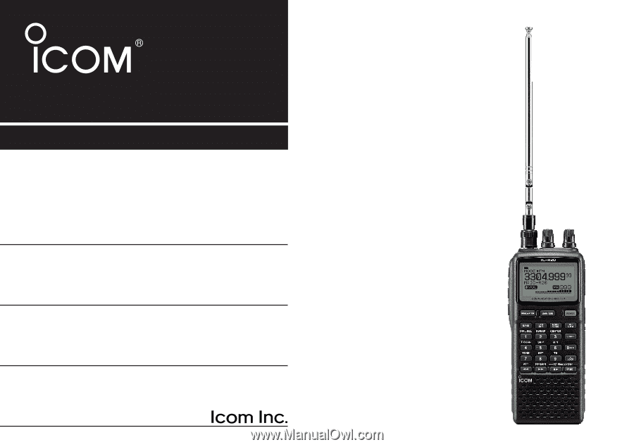
INSTRUCTION MANUAL
iR20
COMMUNICATIONS RECEIVER
This device complies with Part 15 of the FCC rules. Operation is sub-
ject to the following two conditions: (1) This device may not cause
harmful interference, and (2) this device must accept any interference
received, including interference that may cause undesired operation.
WARNING:
MODIFICATION OF THIS DEVICE TO RECEIVE CEL-
LULAR RADIO TELEPHONE SERVICE SIGNALS IS PROHIBITED
UNDER FCC RULES AND FEDERAL LAW.