Philips DVDR985A User manual - Page 14
Connecting to a TV and a Stereo Receiver, Receiver has Dolby Digital, MPEG2, or Digital Theater
 |
UPC - 037849922774
View all Philips DVDR985A manuals
Add to My Manuals
Save this manual to your list of manuals |
Page 14 highlights
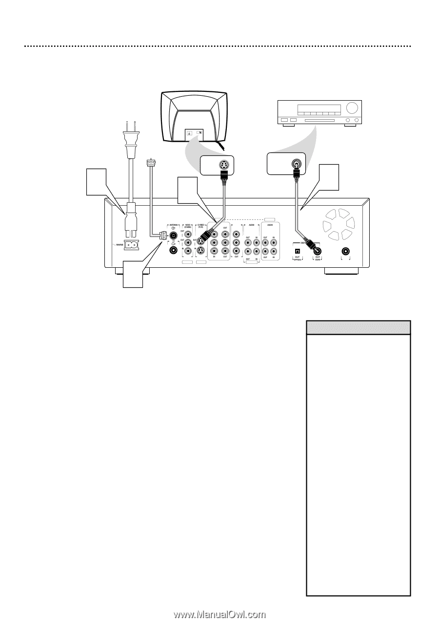
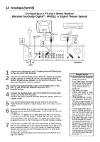
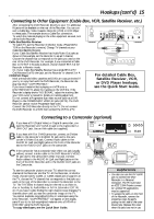
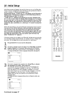
14 Hookups (cont'd) Connecting to a TV and a Stereo Receiver (Receiver has Dolby DigitalTM, MPEG2, or Digital Theater System) 4 Antenna or Cable TV Signal S-AUDIO IN Back of TV (example only) S-VIDEO IN 3 COAXIAL DIGITAL AUDIO IN 1 EXT 2 EXT 3 COMPONENT VIDEO Y Y PB PB PR PR EXT 1 PROG SCAN Y L L PB PR R R EXT 1/2 EXT 3 L R Stereo Receiver (example only) 2 IN RC 6 1 Connect your Antenna or Cable TV signal to the ANTENNA jack on the rear of the DVD Recorder. 2 Connect one of the DVD Recorder's DIGITAL AUDIO OUT jacks (COAX (coaxial) or OPTICAL) to the corresponding DIGITAL AUDIO IN jack on your Stereo. You only need one connection. Use an appropriate digital audio cable (not supplied). 3 Connect the supplied S-Video cable to the S-VIDEO OUT (Y/C) (EXT 1) jack of the DVD Recorder and to the TV's S-VIDEO IN jack. 4 Connect the supplied power cord to the MAINS (AC Power) jack on the rear of the DVD Recorder. Connect the power cords of the DVD Recorder, Stereo, and TV to a power outlet. 5 Turn on the Stereo power and set your Stereo to the correct Digital Audio In channel or sound source. Refer to the Stereo owner's manual. 6 Press the STANDBY-ON y button on the front of the DVD Recorder to turn on the DVD Recorder. The STANDBY-ON light will turn green. If "TURN ON TV" appears on the display panel, you need to turn on your TV and set it to the correct S-Video In channel. (See next step.) This is part of the Initial Setup of the DVD Recorder. You cannot see the Initial Setup screens until you turn on the TV and have it on the right S-Video In channel. 7 Turn on the TV power. Set the TV to the correct S-Video In channel. This is not channel 3 or 4 as it might be when using a VCR. See your TV owner's manual for details. Or, go to your lowest TV channel and change channels down until you see the DVD background picture or Initial Setup screen on the TV screen. The Initial Setup screen will appear the first time you turn on the Recorder. Go to page 16 to continue. Helpful Hints • Set the Digital output accordingly. Details are on page 56. • If your Digital Output setting does not match your Stereo's capabilities, the Stereo may produce a strong, distorted sound or no sound at all. • Your Stereo must support MPEG2, Dolby DigitalTM or Digital Theater System (DTS). Check the Stereo's manual. • To use the VIDEO OUT (CVBS) or COMPONENT VIDEO OUT Y PB PR jacks instead, see pages 10 and 12. Remember to choose the correct Video In channel at the TV. • A small, square, black cap protects the OPTICAL jack when it is not in use. Remove the cap if you want to use the jack; replace the cap when the jack is not in use. • If you plan to watch your TV with the DVD Recorder off, connect the supplied RF coaxial cable to the Recorder's TV jack and to the RF IN or ANTENNA IN jack (75 ohm) on your television. This lets you watch channels at the TV normally when the DVD Recorder is off and will improve the reception at your TV.
-
 1
1 -
2
-
3
-
4
-
5
-
6
-
7
-
8
-
 9
9 -
 10
10 -
 11
11 -
 12
12 -
 13
13 -
 14
14 -
 15
15 -
 16
16 -
 17
17 -
 18
18 -
 19
19 -
20
-
21
-
22
-
23
-
24
-
25
-
26
-
27
-
28
-
29
-
30
-
31
-
32
-
33
-
34
-
35
-
36
-
37
-
38
-
39
-
40
-
41
-
42
-
43
-
44
-
45
-
46
-
47
-
48
-
49
-
50
-
51
-
52
-
53
-
54
-
55
-
56
-
57
-
58
-
59
-
60
-
61
-
62
-
63
-
64
-
65
-
66
-
67
-
68
 |
 |