Philips DVDR985A User manual - Page 24
Rear Panel
 |
UPC - 037849922774
View all Philips DVDR985A manuals
Add to My Manuals
Save this manual to your list of manuals |
Page 24 highlights
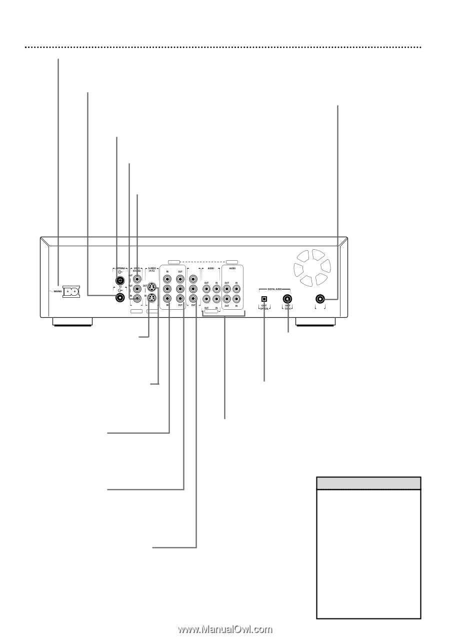
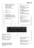
24 Rear Panel MAINS (AC Power) Connect the supplied AC power cord here and to a standard AC outlet after completing all other connections. TV jack Connect the supplied RF coaxial cable to the Recorder's TV jack and to the RF IN or ANTENNA IN jack (75 ohm) on your television. This lets you watch channels at the TV normally when the DVD Recorder is off. ANTENNA jack Connect your antenna or Cable TV signal here. Details are on pages 10-14. VIDEO IN (CVBS) (EXT2) jack Use a video cable to connect this jack to the Video Out jack of other equipment. Details are on page 15. VIDEO OUT (CVBS) (EXT2) jacks Connect the supplied yellow-striped video cable to one of the VIDEO OUT (CVBS) jacks and to the TV's Video In jack. Details are on page 12. Use the extra VIDEO OUT (CVBS) jack to connect the Recorder to other equipment. IN RC 6 jack Connect a wired remote control (not supplied) to the IN RC 6 jack if you prefer. Ask your dealer for details on compatible remotes. The first signals from the remote control may be lost. The remote control supplied with the DVD Recorder will operate all the recorder's features. EXT 3 COMPONENT VIDEO PROG SCAN EXT 3 Y Y PB PB Y L L PB L PR PR PR R R R IN RC 6 EXT 2 EXT 1 EXT 1/2 S-VIDEO IN (Y-C) (EXT1) jack Use an S-video cable to connect this jack to the S-Video Out jack of optional additional equipment. Details are on page 15. S-VIDEO OUT (Y-C) (EXT1) jack Connect the supplied S-Video cable here and to a TV's S-Video In jack. Details are on page 11. COMPONENT VIDEO IN (Y PB PR) (EXT3) jacks Connect these jacks to the Component Video Out jacks of optional additional video equipment (for example, a DVD Player). Details are on page 15. COMPONENT VIDEO OUT (Y PB PR) (EXT3) jacks Connect the supplied three-strand component video cable here and to the Component Video In jacks of a TV. Details are on page 10. PROG SCAN OUT (Y PB PR) jacks (Progressive Scan) Connect these jacks to a TV's Progressive Scan In jacks if the TV has Progressive Scan. Use the supplied three-strand component video cable. Match the cable stripe colors to the jack colors. If your TV does not have Progressive Scan, use the COMPONENT VIDEO OUT jacks instead. Details are on page 10. Also see your TV manual for details. DIGITAL AUDIO OUT COAX (coaxial) jack Connect a digital audio coaxial cable here and to the digital audio coaxial In jack of a Stereo. Details are on page 14. DIGITAL AUDIO OUT OPTICAL jack Connect a digital audio optical cable here and to the digital audio optical In jack of a Stereo. Details are on page 14. AUDIO OUT/ IN (Left/Right) (EXT1/2 and EXT3) jacks Use the supplied audio cables (with red and white stripes) to connect the Recorder's AUDIO OUT jacks to the Audio In jacks of a television or Stereo. Details are on pages 10-13. Use the AUDIO IN jacks when connecting additional equipment to the DVD Recorder. Details are on page 15. Helpful Hints • Each Audio and Video jack is labelled EXT1, EXT2, or EXT3. Use the same EXT (external) number for the audio and video connection to the TV. For example, if you use S-VIDEO OUT, which is EXT1, use the EXT1/2 AUDIO OUT jacks. • Do not touch the inner pins of the jacks on the rear panel. Electrostatic discharge may damage the unit permanently. • You only need one audio and one video connection to a TV. You might not use all the jacks.
-
 1
1 -
2
-
3
-
4
-
5
-
6
-
7
-
8
-
9
-
10
-
11
-
12
-
13
-
14
-
15
-
16
-
17
-
18
-
 19
19 -
 20
20 -
 21
21 -
 22
22 -
 23
23 -
 24
24 -
 25
25 -
 26
26 -
 27
27 -
 28
28 -
 29
29 -
30
-
31
-
32
-
33
-
34
-
35
-
36
-
37
-
38
-
39
-
40
-
41
-
42
-
43
-
44
-
45
-
46
-
47
-
48
-
49
-
50
-
51
-
52
-
53
-
54
-
55
-
56
-
57
-
58
-
59
-
60
-
61
-
62
-
63
-
64
-
65
-
66
-
67
-
68
 |
 |