Pioneer SC-55 Owner's Manual - Page 27
Fm Unbal 75, Am Loop, Zone 2, Zone 3, Optical, Coaxial, Component Video, Component Video Zone 2 Out - hdmi not working
 |
View all Pioneer SC-55 manuals
Add to My Manuals
Save this manual to your list of manuals |
Page 27 highlights
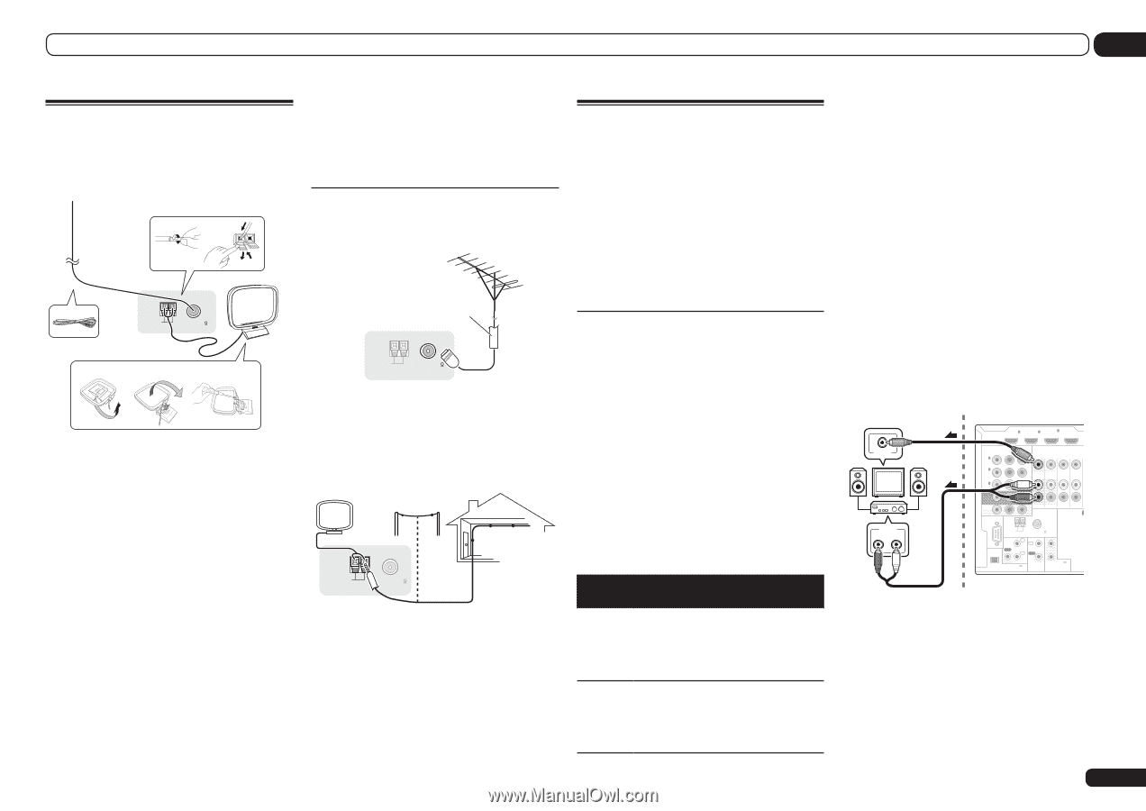
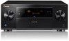
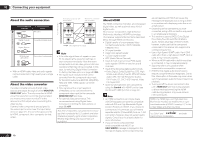
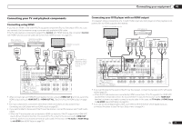
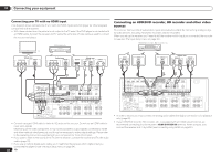
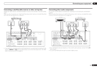
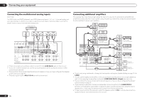
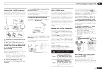
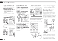
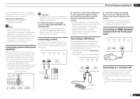
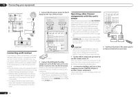
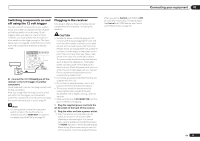
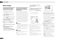
Connecting your equipment 03 Connecting AM/FM antennas Connect the AM loop antenna and the FM wire antenna as shown below. To improve reception and sound quality, connect external antennas (see Connecting external antennas on page 27 ). 1 2 3 5 AM LOOP FM UNBAL 75 4 ANTENNA a b c 1 Pull off the protective shields of both AM antenna wires. 2 Push open the tabs, then insert one wire fully into each terminal, then release the tabs to secure the AM antenna wires. 3 Fix the AM loop antenna to the attached stand. To fix the stand to the antenna, bend in the direction indicated by the arrow (fig. a) then clip the loop onto the stand (fig. b). ! If you plan to mount the AM antenna to a wall or other surface, secure the stand with screws (fig. c) before clipping the loop to the stand. Make sure the reception is clear. 4 Place the AM antenna on a flat surface and in a direction giving the best reception. 5 Connect the FM wire antenna into the FM antenna socket. For best results, extend the FM antenna fully and fix to a wall or door frame. Don't drape loosely or leave coiled up. Connecting external antennas To improve FM reception, connect an external FM antenna to FM UNBAL 75 W. 75 Ω coaxial cable AM LOOP ANTENNA FM UNBAL 75 To improve AM reception, connect a 5 m to 6 m (16 ft. to 20 ft.) length of vinyl-coated wire to the AM LOOP terminals without disconnecting the supplied AM loop antenna. For the best possible reception, suspend horizontally outdoors. Outdoor antenna Indoor antenna (vinyl-coated wire) AM LOOP ANTENNA FM UNBAL 75 5 m to 6 m (16 ft. to 20 ft.) MULTI-ZONE setup This receiver can power up to three independent systems in separate rooms after you have made the proper MULTI-ZONE connections. Different sources can be playing in three zones at the same time or, depending on your needs, the same source can also be used. The main and sub zones have independent power (the main zone power can be off while one (or both) of the sub zones is on) and the sub zones can be controlled by the remote or front panel controls. Making MULTI-ZONE connections It is possible to make these connections if you have a separate TV and speakers for your primary (ZONE 2) sub zone, and a separate TV and a separate amplifier (and speakers) for your secondary (ZONE 3) sub zone. You will also need a separate amplifier if you are not using the MULTI-ZONE setup using speaker terminals (ZONE 2) on page 27 for your primary sub zone. There are two primary sub zone setups possible with this system. Choose whichever works best for you. MULTI-ZONE listening options The following table shows the signals that can be output to ZONE 2 and ZONE 3: Sub Zone ZONE 2 ZONE 3 Input functions available DVD, TV/SAT, DVR/BDR, VIDEO, HOME MEDIA GALLERY, iPod/USB, CD, TUNER, ADAPTER PORT, SIRIUS (Outputs analog audio, composite video and component video.) DVD, TV/SAT, DVR/BDR, VIDEO, HOME MEDIA GALLERY, iPod/USB, CD, TUNER, ADAPTER PORT, SIRIUS (Outputs analog audio, composite video.) It is not possible to down-convert the audio and video input signals from the HDMI input terminals, digital input terminals (OPTICAL and COAXIAL) and the COMPONENT VIDEO input terminals and output them to ZONE 2. Basic MULTI-ZONE setup (ZONE 2) 1 Connect a separate amplifier to the AUDIO ZONE 2 OUT jacks on this receiver. You should have a pair of speakers attached to the sub zone amplifier as shown in the following illustration. 2 Connect a TV monitor to the VIDEO ZONE 2 OUT jack on this receiver. ! COMPONENT VIDEO ZONE 2 OUT can be used to output clear images. ! The GUI screen is not displayed if only the COMPONENT VIDEO ZONE 2 OUT jack is connected. Sub zone (ZONE 2) VIDEO IN AUDIO IN R L Main zone IN 1 IN 2 HDMI ASSIGNABLE 16 ASSIGNABLE Y COMPONENT VIDEO PB PR IN 1 (DVD) IN 4 (VIDEO) BD IN IN 2 (DVR/ BDR) IN 3 (VIDEO) MONITOR OUT ZONE 2 ZONE 3 DVD TV/SAT V OUT OUT IN IN ZONE2 OUT A RS-232C R AM LOOP ANTENNA FM UNBAL 75 IR IN 1 IN 1 SPEAKERS OUT IN 2 OUT 2 (OUTPUT 12 V (OUTPUT 5 V TOTAL 150 mA MAX) EXTENSION 150 mA MAX) CONTROL 12VTRIGGER MULTI-ZONE setup using speaker terminals (ZONE 2) Either the surround back or the front wide speaker terminals can be used as the speaker terminals for ZONE 2. For details, see Determining the speakers' application on page 13 . En 27
-
 1
1 -
2
-
3
-
4
-
5
-
6
-
7
-
8
-
9
-
10
-
11
-
12
-
13
-
14
-
15
-
16
-
17
-
18
-
19
-
20
-
21
-
 22
22 -
 23
23 -
 24
24 -
 25
25 -
 26
26 -
 27
27 -
 28
28 -
 29
29 -
 30
30 -
 31
31 -
 32
32 -
33
-
34
-
35
-
36
-
37
-
38
-
39
-
40
-
41
-
42
-
43
-
44
-
45
-
46
-
47
-
48
-
49
-
50
-
51
-
52
-
53
-
54
-
55
-
56
-
57
-
58
-
59
-
60
-
61
-
62
-
63
-
64
-
65
-
66
-
67
-
68
-
69
-
70
-
71
-
72
-
73
-
74
-
75
-
76
-
77
-
78
-
79
-
80
-
81
-
82
-
83
-
84
-
85
-
86
-
87
-
88
-
89
-
90
-
91
-
92
-
93
-
94
-
95
-
96
-
97
-
98
-
99
-
100
-
101
-
102
-
103
-
104
-
105
-
106
-
107
-
108
 |
 |