Sony HDWD1800 Operation Manual
Sony HDWD1800 Manual
 |
View all Sony HDWD1800 manuals
Add to My Manuals
Save this manual to your list of manuals |
Sony HDWD1800 manual content summary:
- Sony HDWD1800 | Operation Manual - Page 1
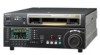
HD DIGITAL VIDEOCASSETTE RECORDER HDW-1800 HDW-D1800 OPERATION MANUAL [English] 1st Edition (Revised 1) - Sony HDWD1800 | Operation Manual - Page 2
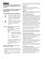
operating and maintenance (servicing) instructions in the literature accompanying the appliance. WARNING: THIS WARNING IS APPLICABLE FOR USA ONLY. If used in USA, use approved in this manual could void your authority to operate this equipment. All interface cables used to connect peripherals must - Sony HDWD1800 | Operation Manual - Page 3
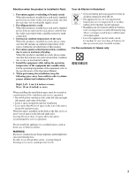
operating temperature of the equipment into consideration For the operating temperature of the equipment, refer to the specifications of the Operation Manual 40 cm or more of space above the unit is recommended for service operation. Do not install the appliance in a confined space, such as book - Sony HDWD1800 | Operation Manual - Page 4
Manual 10 Chapter 4 Recording and Playback 4-1 Recording 33 4-1-1 Preparations for Recording 33 4-1-2 Recording Timecode and User Bit Values 34 4-1-3 Recording 28 3-2-1 Selecting Reference Sync Signal Depending on Operational Status...... 28 3-2-2 Connecting Reference Signals .......... 28 - Sony HDWD1800 | Operation Manual - Page 5
7-2 Recording UMIDs 60 7-3 UMID Output and Display 62 7-3-1 UMID Output Settings 62 7-3-2 UMID Display 62 Appendix Specifications 109 About a "Memory Stick 116 Index 118 Chapter 8 Function Menu 8-1 Overview 64 8-1-1 Function Menu Configuration........... 64 8-1-2 Function Menu Operations - Sony HDWD1800 | Operation Manual - Page 6
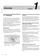
The HDW-1800/D1800 is a high-definition (HD) digital videocassette recorder based on the HDCAM format. This unit uses large scale integrated circuits for signal processing, and has a simple internal construction, allowing it to provide functionality at least equivalent to a conventional VTR in - Sony HDWD1800 | Operation Manual - Page 7
for basic VTR operations are provided in the conventional VTR layout, ensuring continuity with conventional operating panels. Function menu You can use the function buttons on the LCD and the MULTI CONTROL knob to easily carry out many of the operations and make many of the settings supported by the - Sony HDWD1800 | Operation Manual - Page 8
LINK (HDV) Input Board can be installed in this unit to record i.LINK (HDV) signals from HDV devices onto HDCAM tapes. For details on installation, settings, and operations of the HKDW-105 board, refer to the Operation Manual supplied with the board. Note HDV editing is not supported. 8 1-1 Features - Sony HDWD1800 | Operation Manual - Page 9
Chapter 1 Overview 1-2 Example System Configuration The following conceptual diagram shows an example of use. BVE-series editor Tape control Digital cassette HDW-1800/D1800 HDSDI Audio/video server system Video monitor HDSDI/Analog composite Audio monitor Analog audio HDSDI Analog - Sony HDWD1800 | Operation Manual - Page 10
function menu pages and function buttons to configure the function menu of this unit. This manual describes the items related to the function menu as follows, based on the standard factory default settings. Example: Setting F6 (PB/EE) in function menu page P01: HOME This indicates that the PB/EE - Sony HDWD1800 | Operation Manual - Page 11
L1R L2R SDI1 ANA2 L3R SDI3 -30 -40 -60 L4R AES4 -10 -20 -40 L CUE R 3+4 HOME PB/EE PB CONFI ENABLE COUNTER CTL MENU TCG SET Upper control panel (see page 12) Lower control panel (see page 13) KEY INHI CONTROL PANEL Switch panel: access by opening the lower control panel - Sony HDWD1800 | Operation Manual - Page 12
local operation. It is not possible to eject a cassette in another VTR by remote control. d PHONES jack and control Connect stereo headphones with an impedance of 8 Ω, to monitor the sound during recording, playback and editing. The control knob adjusts the volume. It is possible to set - Sony HDWD1800 | Operation Manual - Page 13
L1R L2R SDI1 ANA2 L3R SDI3 -30 -40 -60 L4R AES4 -10 -20 -40 L CUE R 3+4 HOME PB/EE PB CONFI ENABLE COUNTER CTL MENU TCG SET 2 Audio level control knobs (see page 19) 1Menu control section (see page 13) 7 Search control section (see page 21) 6 REC INHI indicator (see page 21 - Sony HDWD1800 | Operation Manual - Page 14
COUNTER CTL MENU TCG SET 3 Audio level meter block 1 4 Audio level meter block 2 5 Time data information 6 Information relating to timecode 2 Function menu information recorded or played back. • Function display mode: The LCD displays timecode, important information about the operating state - Sony HDWD1800 | Operation Manual - Page 15
being played back and upconverted (HDWD1800 only). • Edit state indication CONFI/PREREAD indication The CONFI or PREREAD mode and operating state are indicated as shown below. "CONFI": The HOME PB/EE PB CONFI ENABLE COUNTER CTL MENU TCG SET Function button display area • Name of function menu page - Sony HDWD1800 | Operation Manual - Page 16
is shown only if a Digital Betacam or HDCAM tape is currently loaded in the unit. There for display. For details on "FINE" and "FULL", see the settings of F4 (MT.SCALE) in function menu page P08: AUD INP HDW-D1800. • Data/Emphasis indication This indicates the attributes of the signals to be recorded - Sony HDWD1800 | Operation Manual - Page 17
used the peak value 0, a marker displays the meter headroom setting value. One of the following values is displayed: -20 data display This displays values such as timecode values, user bit values, and CTL HDCAM HD Orange IMX IMX Green (HDW-D1800 only) D-BETA DB Blue (Dark blue) (HDWD1800 - Sony HDWD1800 | Operation Manual - Page 18
is in the "INT-PSET" state. "F-RUN": The timecode generator always runs. "R-RUN": The timecode generator runs only when recording is in progress. • VTR control mode This indicates the control status of the VTR. " " (blank): The VTR is being operated as a standalone unit. "PARARUN": This unit and - Sony HDWD1800 | Operation Manual - Page 19
. • P1: HOME button This button selects the HOME function menu page. The HOME page allows you to make settings for basic VTR and editing operations. • P2: TC button This button selects the TC (timecode) function menu page. The TC page allows you to change between LTC and VITC, change between DF and - Sony HDWD1800 | Operation Manual - Page 20
on error messages, refer to the Maintenance Manual Volume 1. KEY INHI (inhibit) indicator This indicator lights when the KEY INHI switch on the switch panel (see page 22) is set to "ON". 4 MULTI CONTROL knob and PUSH/ SHIFT indicator In function menu operations, turn the MULTI CONTROL knob to change - Sony HDWD1800 | Operation Manual - Page 21
operate Record inhibit Record permit REC INHI indicator state Lit Lit a) Off a) It is possible to make the indicator flash by setting setup menu item 107. 7 Search control section 1 SHUTTLE button 2 JOG button 3 VAR button SHUTTLE REVERSE JOG VAR FORWAR 4 Search dial a SHUTTLE button To use - Sony HDWD1800 | Operation Manual - Page 22
the range in which noiseless playback is possible. • HDCAM: Maximum 51 steps • Digital Betacam, MPEG IMX: on operation, see page 39. Setting setup menu item 101 (see page 81) to KEY enables you to use only menu settings, refer to the Maintenance Manual Volume 1. c KEY INHI (inhibit) switch Setting - Sony HDWD1800 | Operation Manual - Page 23
5 Power supply section (see page 25) 7 Timecode input/output section (see page 26) 8 Audio audio signals to channels 1 and 2. You can record analog audio signals input to these connectors to any audio AUDIO INPUT CH1 and CH2 LEVEL switch settings Audio input level and impedance Level Impedance - Sony HDWD1800 | Operation Manual - Page 24
When using the loop-through connection, set the switch to the "OFF" position, and otherwise set to the "ON" position. These connectors and switch operate only of 4 sets (8 channels: CH1/2, CH3/4, CH5/6, CH7/8) of AES/EBU format digital audio signals. However, the HDW-1800 supports 2 sets only (4 - Sony HDWD1800 | Operation Manual - Page 25
superimposed timecode, menu settings, alarm Installation Manual. HDCAM VTR, and a BVE-series BVE-700/900/910/2000/9000/9000P/ 9100/9100P or other editor, connect the optional 9-pin remote control cable from the other unit to this connector. Depending on the setting in setup menu item 211, you can use - Sony HDWD1800 | Operation Manual - Page 26
outputs a timecode according to the operating state of the unit, as follows: • During playback: the playback timecode By setting setup menu item 606, you can also output the timecode from the internal timecode generator locked to the playback timecode. • During recording: the timecode generated by - Sony HDWD1800 | Operation Manual - Page 27
unit can input serial digital signals (video and audio) from another digital VTR such as the HDW-500/F500/ A2100/M2100. The following figure shows example connections to use this unit (HDW-1800/D1800) as recorder and the HDW-A2100/M2000 unit as player. Reference signal 75Ω termination switch: OFF - Sony HDWD1800 | Operation Manual - Page 28
334 operational signal setting status a) setting NORMAL EE PB EDIT REC INPUT EE PB EDIT REC - EE PB EDIT REC REF INPUT REF INPUT a) EE: In E-E mode PB: Playing back (normal playback, jog mode, shuttle mode, variable speed mode and stop mode) EDIT: Edit preset enabled REC: Recording - Sony HDWD1800 | Operation Manual - Page 29
REF. VIDEO 75Ω termination switch: ON HDSDI INPUT OUTPUT COMPOSITE SD video monitor SDI OUTPUT HDW-1800/D1800 3-3 Setup The principal setup operations before operating this unit can be carried out using setup menus. The setup menus of this unit comprise a basic setup menu and an extended - Sony HDWD1800 | Operation Manual - Page 30
mode (Recorder/player selection) The indication changes as follows, according to the VTR control mode (the setting of F6 (R/P SEL) in function menu page P06: EDIT). P: Two-unit editing is currently being carried out and the VTR (player) connected by a 9-pin remote cable is being operated from the - Sony HDWD1800 | Operation Manual - Page 31
menu item 111) a) Initial speed setting or stored speed setting Chapter 3 Preparations A B C Display Operation mode Block A Block B TAPE UNTHREAD mode (see normal speed page 39) (%) REC Record mode (servo unocked) REC LOCK Record mode (servo locked) EDIT Edit mode (servo unlocked - Sony HDWD1800 | Operation Manual - Page 32
uses the following HDCAM cassettes for both recording and playback. HDCAM cassettes Small cassettes Large cassettes BCT-6HD/12HD/22HD/32HD/40HD BCT-34HDL/64HDL/94HDL/124HDL The HDW-D1800 Ejecting is a local operation. It is not possible to eject a cassette in another VTR by remote control. If - Sony HDWD1800 | Operation Manual - Page 33
SDI1 ANA2 L3R SDI3 -30 -40 -60 L4R AES4 -10 -20 -40 L CUE R 3+4 HOME PB/EE PB CONFI ENABLE COUNTER CTL MENU TCG SET Adjust the audio recording levels (see page 19). Select the input audio signal (see page 69). Select the input video signal (see page 65). Select the audio channel - Sony HDWD1800 | Operation Manual - Page 34
(page 19) and the F6 (PB/EE) setting in function menu page P01: HOME (page 65). To set an initial value then record the timecode If necessary, change the settings in function menu page P02: TC (see page 66). To set an initial timecode value Use the following procedure. To change the display range - Sony HDWD1800 | Operation Manual - Page 35
generator with an external signal Use this method to synchronize the timecode generators of multiple VTRs, or to record the playback timecode signal from an external VTR without deterioration of the signal waveform. In this case the RUN and DF settings are ignored. You can synchronize the internal - Sony HDWD1800 | Operation Manual - Page 36
Playback disconnected, the internal timecode generator continues to run. 4-1-3 Recording Procedure Use the following procedure. 12 3 1 Insert a cassette. For details, see the section "To insert a cassette" (page 32). 2 Hold down the REC button, and press the PLAY button. Recording starts, the servo - Sony HDWD1800 | Operation Manual - Page 37
P01: HOME can be used to select CTL (control), timecode, or user bit values. When you select timecode, the data to be displayed is determined by the setting (LTC, AUTO, or VITC) of F10 (TCR) in function menu page P02: TC as follows. TCR setting Displayed data LTC LTC recorded on tape AUTO LTC - Sony HDWD1800 | Operation Manual - Page 38
using the capstan override function The playback speed is adjusted temporarily according to the angular position of the search dial, to align the playback phase with another VTR disabled by changing the setting in setup menu item playback speed is as follows. • HDCAM tape: ±50 times normal speed (59 - Sony HDWD1800 | Operation Manual - Page 39
Recording can be disabled by changing the setting in setup menu item 101. speed within the following ranges: • HDCAM: -1 to +2 times normal speed use the capstan override function to adjust the playback speed temporarily. This function is convenient for playback phase synchronization with another VTR - Sony HDWD1800 | Operation Manual - Page 40
out any other operation to exit the tape speed override mode. For details of setup menu operations, see Section "9-2 Setup Menu Operations" (page 75 live broadcast of a sporting event you can set the start and end points of highlights while recording, and then provide immediate DMC playback of those - Sony HDWD1800 | Operation Manual - Page 41
(DMC) begins to flash, and playback begins at the speed set in step 4. 6 Rotate the search dial to vary the playback operating mistakes we recommend that you use the VTR in standalone mode when carrying out DMC playback. • When using two VTRs connected for editing, you can only use the recorder VTR - Sony HDWD1800 | Operation Manual - Page 42
Chapter 4 Recording and Playback To start playback at the on-air cue from the on-air start point Use the following procedure. 1 Holding down the SHIFT/ENTRY button, select F3 (REVIEW) in function menu page P06: EDIT. F3 (REVIEW) lights, and the tape is - Sony HDWD1800 | Operation Manual - Page 43
the edit IN point. Using setup menu item 610, it is also possible to record timecode according to the settings in the function menu. Sequence of editing operations The following flowchart outlines the sequence of operations in automatic editing with two VTRs. 5-1-1 Overview Selecting the editing - Sony HDWD1800 | Operation Manual - Page 44
Before you start editing, make necessary switch settings. Recorder settings POWER switch: "I" side (on) (see page 12) REMOTE buttons (see page 12): OFF HDW-1800/D1800 HOME VIDEO IN SDI EDIT E.PRESET CLR CNT 59.94 SDI 10801080 2F ASM CONFI LTC D F VITC LTC EXT-LTC R-RUN PARARUN 12:34:47 - Sony HDWD1800 | Operation Manual - Page 45
P06: EDIT to select the player or recorder to be set the edit points. Each time F6 (R/P SEL) is selected, the target VTR changes. To set split edit points In split editing, you can set the edit points for audio and video independently. Set the audio edit points using F7 (AUD IN) and F8 (AUD OUT - Sony HDWD1800 | Operation Manual - Page 46
as the player When it is not possible to set audio and video edit points individually on the VTR you are using as the player, you can carry out split editing by setting the audio IN and OUT points and three video edit points on the recorder (this unit). To display the time data for - Sony HDWD1800 | Operation Manual - Page 47
set: the duration of the segment between the set edit point and the current tape position • When no edit point is set F6 (R/P SEL) to select the VTR you want to modify the edit point operation. In this case, modify the erroneous edit point, or delete and enter it correctly. To modify an edit point Use - Sony HDWD1800 | Operation Manual - Page 48
Preroll Use the following procedure. Chapter 5 Editing 1,2 1 In function menu page P06: EDIT, select F6 (R/P SEL) to select the VTR you use menu item 001 to change this to any value from 0 to 30 seconds. If you change the preroll time, make sure that the setting is not longer than the recording - Sony HDWD1800 | Operation Manual - Page 49
automatic editing, the recorder and player operate as shown in the figure above, to record the video and recorder. 2 In the basic setup menu, set menu item 008 to "AUTO". 3 Select the player (PLAYER) using F6 (R/P SEL) in function menu page P06: EDIT on the recorder side. This makes the recorder - Sony HDWD1800 | Operation Manual - Page 50
recorded correctly is used for insert editing, noise or breakup can occur in the audio and video when that section is played back. To start automatic editing When you finish setting you can carry out a preview or automatic editing operation again by holding down the SHIFT/ENTRY button and selecting - Sony HDWD1800 | Operation Manual - Page 51
. Preroll Recorder IN point DMC editing Tape transport OUT point Postroll Playback Playback Preroll time x initial speed Player IN point Stop Postroll time x final speed Time flow Tape runs at initial speed 5-2-2 Carrying Out DMC Editing To set the edit points and player speed Use the - Sony HDWD1800 | Operation Manual - Page 52
set an edit point. 5 Select F6 (R/P SEL) to select the player (PLAYER), and set the player edit IN point using the same procedure as step 4. Note It is not possible to set is prerolled and then the recorder starts operating at normal speed and the player starts at the set initial speed. 9 On reaching - Sony HDWD1800 | Operation Manual - Page 53
an automatic editing, the recorder automatically returns to the OUT point. For the second and subsequent editing operations, you can continue editing , to carry out continuous editing use the following procedure. 1 Set the player IN and OUT points. Recorder OUT point for the previous editing - Sony HDWD1800 | Operation Manual - Page 54
, and it is now possible to carry out automatic editing. If necessary, you can also set the OUT point in advance. 5-3-4 Preread Editing Video and digital audio signals already recorded on the tape can be used as an edit source for insert editing. This type of editing is called "preread editing - Sony HDWD1800 | Operation Manual - Page 55
mark is written automatically at the start of recording. Possible Shot mark 1 and shot Written by a manual shot mark 2 mark operation during recording or editing. Written by a button operation during crash recording or assemble editing. A menu setting determines the type of mark to be written - Sony HDWD1800 | Operation Manual - Page 56
recording start mark for each of the three recording modes (CRASH REC, ASSEMBLE, INSERT). When you set a particular mode to "ON", a recording start mark is written on the tape each time you start recording in that mode. Note EXIT When using , carry out the reading operation again. Data written in - Sony HDWD1800 | Operation Manual - Page 57
procedure, see page 58. 6-2-3 Shot Mark List Operations To display the shot mark list Holding down the SHOT MRK MEMO REC/ERS ERASE REC ERASE SETTING SHOT MRK MARK LIST PREROLL EXIT Example 24 017 #R 10:10:36:00 Timecode Shot mark type R: recording start mark S1: shot mark 1 S2: shot mark 2 - Sony HDWD1800 | Operation Manual - Page 58
operation to remove a memo mark. To select the types of shot mark to be read in the list For each types of shot mark (recording type. 3 Select F4 (ON) or F3 (OFF) to set "ON" (displayed) or "OFF" (not displayed). 4 list To delete an individual shot mark Use the following procedure. 3 1,2,3 1 With - Sony HDWD1800 | Operation Manual - Page 59
shot marks from the tape To erase a shot mark, use the following procedure. Note If you erase a shot mark from erased, close the shot mark list. The F2 (REC/ERS) setting returns to "OFF" when shot mark erasure is complete. 6-2-4 Cuing You cannot use the above procedure to cue up to a virtual shot mark - Sony HDWD1800 | Operation Manual - Page 60
It has been internationally standardized in SMPTE Standard 330M. This unit supports recording and output of UMIDs. The UMID is made up of a section type of UMID to record Select whether to record a Basic UMID or an Extended UMID by using setup menu item 655 "UMID RECORDING". For more information - Sony HDWD1800 | Operation Manual - Page 61
procedure. For more information about basic setup menu operations, see Section "9-2 Setup Menu Operations" (page 75). 1 Set setup menu item 029 to "on" and select F9 (SET). ITEM-029 STORED OWNERSHIP *COUNTRY ORGANIZATION USER - ABCD - EFGH - IJKL 2 Use F1 (PREV) or F2 (NEXT) to select the - Sony HDWD1800 | Operation Manual - Page 62
settings using setup menu item 651 "UMID OUTPUT". For more information about setup menu item 651, see page 92. 7-3-2 UMID Display During recording F2 (UMID). For more information about function menu operations, see Section "8-1-2 Function Menu Operations" (page 64). The UMID appears in the menu - Sony HDWD1800 | Operation Manual - Page 63
above When menu item 656 "MATERIAL NO." is set to "NEW", it is generated by SMPTE method seconds : frame) converted to UTC. recording device (Recorder), and "T" is shown for Target supportive geodetic apparatus was used. A space (blank) is displayed when no supportive geodetic apparatus was used - Sony HDWD1800 | Operation Manual - Page 64
settings other than those made with the basic operation buttons, such as selection of input video signals and editing of timecode 2 (no functions defined) Note The explanations in this manual are based on the factory default settings. The following shows an example display of the function menu - Sony HDWD1800 | Operation Manual - Page 65
this manual are based on the factory default standard settings. P01: HOME This is a function menu page for setting basic items. Item Setting whether or not to use the CONFI playback function when recording. a) ENABLE: Use the CONFI playback function. DISABL: Do not use the CONFI playback - Sony HDWD1800 | Operation Manual - Page 66
continues to increase as long as the unit is powered on, regardless of the unit's operating mode. REC: Timecode increases during recording only. If you select this mode, you should also set F1 (TCG SRC) to "INTERNAL", and set F2 (TCG MODE) to "PRESET" in this menu page. F4 (DROP FRM) In 59.94i - Sony HDWD1800 | Operation Manual - Page 67
Select the reference signal of this unit, according to the settings in setup menu items 309 and 334, and this unit's operating state. REF: Use the signal input to a REF. VIDEO INPUT connector as the reference signal. When recording, input digital audio signals and video signals must be synchronized - Sony HDWD1800 | Operation Manual - Page 68
manually set values, the level is set to the standard value. Manual setting: With the displayed setting text information including timecode, menu settings, and error . TOTAL: Display total recorded time. REMAIN: Display setting the freeze operation is set to "MOMNT". When setup menu item 904 is set - Sony HDWD1800 | Operation Manual - Page 69
recording to tape depending on the setting in setup menu item 310. OFF: Do not inhibit recording to tape. F2 (INS TC) Edit preset setting for timecode track F3 (INS CUE) Edit preset setting monitor output channel operation F10 (RETURN) Return to P08: AUD INP a) For HDCAM and Digital Betacam - Sony HDWD1800 | Operation Manual - Page 70
(1 to 4) using this item (REC TRAC) and specify the audio input channel from which signals are recorded to the specified audio track using F1 (INP A1 Setting F1 (No function assigned) F2 (REC/ERS) Settings for the shot mark recording/ erasing operation F3 (REC) Shot mark recording operation - Sony HDWD1800 | Operation Manual - Page 71
. For more information about error log operations, refer to the Maintenance Manual Volume 1. Item Setting F1 (ERROR) List display of error description (initial setting) F2 (DATE) List display of error occurrence date and time F3 (TC) List display of timecode at error occurrence F4 (DETAIL - Sony HDWD1800 | Operation Manual - Page 72
page. P116: MAINTE This is a function menu page for maintenance menu operations. For more information about maintenance menu, refer to the Maintenance Manual Volume 1. Item F1 F2 F3 F4 F5 F6 F7 F8 F9 (SET) F10 (EXIT) Setting (No function assigned) (No function assigned) (No function assigned) (No - Sony HDWD1800 | Operation Manual - Page 73
assigned) (No function assigned) Return to the previous page. P118: SETUP (TC/UB SETTING) This is a function menu page for selecting timecode (TC) or user bit (UB) digits to set in the setup menu. This is for setting the ID code and starting TC in setup menu items 603 and 621, respectively. Item - Sony HDWD1800 | Operation Manual - Page 74
83 200 to 299 control interface Items Settings relating to editing 300 to 399 operations Page 84 Items Settings relating to preroll 400 to 499 Page 87 Items Settings relating to tape 500 to 599 protection Page 88 Items Settings relating to the timecode Page 89 600 to 650 generator - Sony HDWD1800 | Operation Manual - Page 75
F3 CATEG - HO2:DRUM HOURS - 52 F8 F4 CATEG + SET F9 F5 EXIT F10 For basic operations in the menu item, see page 64. To display menus on F9 (SET) is not selected, all changes are cancelled. To change the settings of menu items with subitems After selecting a desired sub-item using the - Sony HDWD1800 | Operation Manual - Page 76
SETUP" to "ON". The message "Push SET button!" appears. 2 Select F9 (SET). 3 Select F9 (SET) again. The menu settings are saved. To recall the BANK4 settings (menu item B20) To set the current menu settings to the BANK4 settings, carry out the following operation. 1 Carry out steps 1 to 3 of the - Sony HDWD1800 | Operation Manual - Page 77
operations (menu items B01 to B13) This unit saves menu settings in what are termed "menu banks". Saved sets of menu settings can be recalled for use as required. To save the current active menu settings Set 4, refer to the Maintenance Manual. Current active menu settings Recall (B01) Save (B11 - Sony HDWD1800 | Operation Manual - Page 78
only to the recorder, determines SELECTION FOR VTR- whether the recorder is forced into E-E mode when the recorder's PLAYER button TO-VTR EDIT is pressed to view the player's playback signals on the monitor. MANU: Do not force the recorder into E-E mode. AUTO: Set the recorder to E-E mode, so - Sony HDWD1800 | Operation Manual - Page 79
with white outline Determine the vertical size of characters such as timecode output from the COMPOSITE VIDEO OUTPUT 3 (SUPER) connector, SDI from another device, you can select the operable buttons on the control panel from the following sub-items. The settings of each sub-item are as follows. - Sony HDWD1800 | Operation Manual - Page 80
to "ON" to save the current menu settings to menu bank 3. Set to "ON" to reset the current menu settings to factory default values. a) When setting items 002 and 003, watch the monitor screen, and adjust to the required state. b) Note When displaying timecode values, there is a slight time delay - Sony HDWD1800 | Operation Manual - Page 81
Settings Select how the unit enters the search mode. DIAL: Turning the search dial switches to search mode at all times except during recording .94i or 29.97PsF mode) • HDCAM cassette/Digital Betacam cassette: 50 times normal of the setting of CAPSTN in function menu. Note When operating in 24PsF - Sony HDWD1800 | Operation Manual - Page 82
set to "OFF" and the record inhibit plug on the cassette is pressed in. OFF: Do not flash. ON: Flash. 108 AUTO EE SELECT Select the VTR the range -3 to +3 (±2 during HDCAM tape playback), as shown in figure " CONTROL PANEL Select which switch and button operations can be carried out from the - Sony HDWD1800 | Operation Manual - Page 83
field playback. Note For HDCAM tapes recorded in PsF mode, playback is Settings Select whether to make syncronous operation for two or more VTRs. DIS: No synchronized operation ENA: Make syncronous operation Note To make syncronous operation for two or more VTRs, set item 201 to "ENA" on all VTRs - Sony HDWD1800 | Operation Manual - Page 84
Maintenance Manual Volume 1. 212 VIDEO REMOTE Make settings for control from such as HKDV-900/503 via the VIDEO CONTROL CONTROL SELECT (9P) connector. Sub-item 1 IMAGE Select whether to control the upconverter or downconverter when controlling the ENHANCER image enhancer. (HDW-D1800 only - Sony HDWD1800 | Operation Manual - Page 85
point. Editing is not executed if an erroneous edit point is set (the name of an edit button is flashing). 309 SERVO/AV REFERENCE Select the servo reference signal. SEL AUTO1: During recording, the input video signal is used as the servo reference signal. During playback, the signal selected by - Sony HDWD1800 | Operation Manual - Page 86
/OUT FI/FO: Fade in and fade out t IN/OUT 318 EDIT RETRY t t: Time set by menu item 803 "DIGITAL AUDIO FADE TIME" For two-VTR editing, and when this unit is used as the recorder. Select the operation if the recorder was not synchronized in time. OFF: Editing is not carried out, and the unit - Sony HDWD1800 | Operation Manual - Page 87
. SD: Use a reference video signal. Input a video signal with chroma burst (VBS) or a monochrome video signal (VS) to a REF. VIDEO INPUT connector. Note When operating in 24PsF or 23.98PsF mode, "HD" is selected. 338 OUTPUT AUDIO/TC Set the audio (AES/EBU and analog) and timecode output phase - Sony HDWD1800 | Operation Manual - Page 88
to protect the video heads and tape. 0.5S to 8M to 30M: Set the value in the range 0.5 seconds to 30 minutes. Select the protection T.REL: Switch to tension release mode (the tape tension slackened). Select the operation of the protection mode to protect the video heads and tape when stopped (the - Sony HDWD1800 | Operation Manual - Page 89
. 604 ID CODE SW Select whether to record the ID code, set using menu item 603 in the user bits. OFF: Record the normal data in the user bits. ON: Record the ID code in the user bits. 605 TCG REGEN MODE Select the signals to be regenerated when the timecode generator is in regeneration mode - Sony HDWD1800 | Operation Manual - Page 90
F2 (TCG MODE) in function menu page P02: TC, the timecode generator regenerates according to the timecode on the tape. MANU: Regardless of whether this unit is the recorder or player, the timecode generator operates in accordance with the settings of F1 (TCG SRC) and F2 (TCG MODE) in function menu - Sony HDWD1800 | Operation Manual - Page 91
to the timecode generator (Continued) Item number Item name Settings 618 UPCONV Select the source for HDSDI embedded VITC which is output after up-conversion during EMBEDDED VITC playback of SD-format tape. (HDW-D1800 only. Invalid in 24PsF or 23.98PsF mode.) VITC: Select VITC recorded on SD - Sony HDWD1800 | Operation Manual - Page 92
to 650, relating to the timecode generator (Continued) Item number Item name Settings 631 REC START MARK MODE Sub-item 1 CRASH REC OFF: Do not write recording start marks. ON: Write recording start marks during normal recording. 2 ASSEMBLE OFF: Do not write recording start marks. ON: Write - Sony HDWD1800 | Operation Manual - Page 93
Pack Date/Time (when) changes with each frame. • The Source Pack Spatial Co-ordinates (where) are not recorded. • The Source Pack Stored Ownership (who) can be set. (See the section "To set Stored Ownership" (page 61)). Menu items in the range 700 to 799, relating to video control Item number - Sony HDWD1800 | Operation Manual - Page 94
HDW- D1800 only) 707 FORCED VERTICAL INTERPOLATION OFF 710 INTERNAL VIDEO SIGNAL GENERATOR 713 VIDEO SETUP REFERENCE LEVEL (In 59.94i or 29.97PsF mode only) Sub-Item OUTPUT LEVEL (59.94i mode) Settings During recording signal is generated. (The VTR operates normally.) CB: Color bar - Sony HDWD1800 | Operation Manual - Page 95
PRESET is lit. INT: The video playback signal output phase is the same as the output phase in E- E mode. Use this setting when editing with a single VTR, or when previewing while monitoring the VTR output signal. EXT: The video playback signal output phase is the same as the phase of an input video - Sony HDWD1800 | Operation Manual - Page 96
) Note The cross-fade or fade in/out operation means that the recording is rewritten from the OUT point for the length specified by this setting. Even at the minimum 5ms setting, a length of recording corresponding to a field is rewritten. To avoid rewriting, set menu item 317 "AUDIO EDIT MODE" to - Sony HDWD1800 | Operation Manual - Page 97
INTERNAL AUDIO SIGNAL GENERATOR 810 AUDIO EDIT PREVIEW SWITCHER 823 NON-AUDIO FLAG PB (HDW-D1800 only) Sub-item 1 CH1/CH2 Settings Select the operation of the internal audio test signal generator. OFF: No operation SILNC: Silent signal 1KHZ: At 1 kHz, -20 dB FS sine wave is supplied to - Sony HDWD1800 | Operation Manual - Page 98
PB VOLUME SELECT (HDW-D1800 only) Sub-item 0 ALL CH 1 CH1 2 CH2 3 CH3 4 CH4 5 CH5 6 CH6 7 CH7 8 CH8 833 CUE AUDIO INPUT SELECT Settings Selects which PB knobs are assigned for the playback of digital audio channels. DEFAULT: Use the following settings. CH1: Control knob - Sony HDWD1800 | Operation Manual - Page 99
, regardless of the above settings, when this unit is switched to any of the following modes: Edit preset function on Cue up Recording 906 STOP FREEZE CONTROL Select whether the STOP FREEZE function should operate. DIS: Do not operate. ENA: Operate. stby: Operate only in standby mode. 918 - Sony HDWD1800 | Operation Manual - Page 100
the squeeze mode. 951 H CROP POSITION (UC) Adjust the "H-crop" (the horizontal position when inserting in edge crop mode) of (HDW-D1800 only. Invalid the upconverter output when menu item 950 is set to "crop". in 24PsF or 23.98PsF mode) -120 to 0 to 120 100 9-4 Items in the Extended Setup Menu - Sony HDWD1800 | Operation Manual - Page 101
0 to 120 953 UP CONVERTER Select the original picture to use when converting SD to HD. PROCESS SELECT (HDW-D1800 only. Invalid in 24PsF or 23.98PsF mode) FIELD: Use field picture. FRAME: Use frame picture. adapt (standard mode): Set the ratio of converting from frames or fields to the standard - Sony HDWD1800 | Operation Manual - Page 102
COLOR (UC) (HDW-D1800 only. Invalid in 24PsF or 23.98PsF mode) Settings Set the color of the HDW-1800 (SYL) units having a serial number 10059 or higher, on HDW-1800 (CNB) units having a serial number 51001 or higher, HDW-D1800 (SYL) units having a serial number 10037 or higher, and HDW-D1800 - Sony HDWD1800 | Operation Manual - Page 103
to the Installation Manual. 10-2 Head Cleaning To clean the video heads and audio heads, always use the special-purpose BCT-HD12CL cleaning cassette. If you insert the cleaning cassette, it is automatically ejected after a head cleaning operation for 10 seconds. Follow the instructions with the - Sony HDWD1800 | Operation Manual - Page 104
problem is detected, it displays an error message in the time data display and on the video monitor. If an error message appears, contact your Sony service the time data display If a problem is detected, the ALARM indicator the location of the problem. ERROR-01 REEL TROUBLE-1 Error message displays • - Sony HDWD1800 | Operation Manual - Page 105
REEL TROUBLE REEL TROUBLE REEL TROUBLE REEL TROUBLE REEL TROUBLE TAPE TENSION CAPSTAN TROUBLE DRUM TROUBLE TH/ been detected in the threading or unthreading operation. Tape slacking or tape breaking has been up reel locking has been detected in recording or playback mode. Abnormal tape transport - Sony HDWD1800 | Operation Manual - Page 106
operational history of the unit in each corresponding mode. Use it as a guide in scheduling periodic maintenance. Display modes of the hours meter H01: OPERATION of hours the unit has been in fast forward, rewind, playback, search, recording or editing (except for stop and still) mode in units of 1 - Sony HDWD1800 | Operation Manual - Page 107
10-5-2 Maintenance Timings Use the following table as a timing guide for checking and components, refer to the Maintenance Manual Volume 1. Component Digital hours time (H03) Fan motor (card) Operation time (H01) Fan motor (MD) Sony service or marketing representative. 107 10-5 Regular Checks - Sony HDWD1800 | Operation Manual - Page 108
blue), or flashing. In addition, over a long period of use, because of the physical characteristics of the liquid crystal display, such "stuck" pixels may appear spontaneously. These problems are not a malfunction. Note that any such problems have no effect on recorded data. 108 10-6 About the LCD - Sony HDWD1800 | Operation Manual - Page 109
.7 mm/s (59.94i, 29.97PsF) 80.6 mm/s (50i, 25PsF), 77.4 mm/s (24PsF, 23.98PsF) Digital Betacam: 96.7 mm/s (HDW-D1800 only) MPEG IMX: 64.5 mm/s (59.94i), 53.8 mm/s (50i) (HDW-D1800 only) HDCAM record/playback time 124 minutes with BCT-124HDL (59.94i, 29.97PsF) 149 minutes with BCT-124HDL (50i, 25PsF - Sony HDWD1800 | Operation Manual - Page 110
/ 124HDL Digital Betacam cassettes (HDW- D1800 only) MPEG IMX cassettes (HDW-D1800 only) Digital video system Digital video signal system Sampling frequency Y: 74.25 MHz R-Y/B-Y: 37.125 MHz Quantization 8 bits/sample Compression Coefficient recording system Channel coding S-I-NRZI PR - Sony HDWD1800 | Operation Manual - Page 111
low impedance, balanced AUDIO OUTPUT (AES/EBU) CH1/2, CH3/4, CH5/6, CH7/8 BNC (4) Complies with AES-3id-1995 (CH1/2 and CH3/4 only for HDW- 1800) MONITOR OUTPUT (L/R) XLR 3-pin, male (2) +4 dBm at 600 Ω load, low impedance, balanced TIME CODE OUT XLR 3-pin, male (1) 2.2 Vp-p, low impedance, balanced - Sony HDWD1800 | Operation Manual - Page 112
for rack mounting (4) CD-ROM Manual (1) Installation Manual (1) Operation Guide (1) Optional accessories HKDW-104 Pull- RECORDING MEDIA, EXTERNAL STORAGE SYSTEMS OR ANY OTHER MEDIA OR STORAGE SYSTEMS TO RECORD CONTENT OF ANY TYPE. • Always verify that the unit is operating properly before use. SONY - Sony HDWD1800 | Operation Manual - Page 113
DC values. c) Select which menu item is set, 713 or 718 with the sub-item of menu item 212 "VIDEO REMOTE CONTROL SELECT". Menu items specify output as follows. HD: HDSDI output during HDCAM playback DC: Downconverted SD (D1 SDI/COMPOSITE) output during HDCAM playback SD: SD (D1 SDI/COMPOSITE) output - Sony HDWD1800 | Operation Manual - Page 114
) output and composite output have the same phase. • Item M3A2 is valid HDW-D1800 only. For details of the audio/timecode output phase, see setup menu item 338. Compatibility of playback tape formats Playback tape format HDCAM Digital Betacam a) MPEG IMX a) 23.98PsF 24PsF 25PsF 50i 29.97PsF 59 - Sony HDWD1800 | Operation Manual - Page 115
conversion outputs Playback tape format System frequency 23.98PsF 24PsF 25PsF 50i HDCAM 23.98PsF No No 24PsF 25PsF No 50i Yes a) 29. /59.94i, output is upconverted to 1080/59.94i. e) HDW-D1800 only 29.97PsF No 59.94i No Yes b) No No Yes d) No Yes d) Appendix 115 Specifications - Sony HDWD1800 | Operation Manual - Page 116
MagicGate? MagicGate is copyright protection technology that uses encryption technology. Before using a "Memory Stick" Terminal Write-protect tab Labeling position • When you set the "Memory Stick" erasure prevention switch to "LOCK", data cannot be recorded, edited, or erased. • Data may be damaged - Sony HDWD1800 | Operation Manual - Page 117
data frequently. In no event will Sony be liable for any loss of data. • Unauthorized recording may be contrary to the provisions of copyright law. When you use a "Memory Stick" that has been pre-recorded, be sure that the material has been recorded in accordance with copyright and other applicable - Sony HDWD1800 | Operation Manual - Page 118
66 E Edit point cue-up and preroll 48 modifying and deleting 47 setting 45 Editing automatic editing 43 continuous editing 53 cross-fade editing 7, 86 -user-definable 69 operations 64 overview 64 user-definable 65 Function selection buttons 13 G Ground terminal 25 H HDCAM 6 cassettes 32 HDSDI - Sony HDWD1800 | Operation Manual - Page 119
Setting a user bit value 35 Setup 29 Setup menu basic menu items 78 configuration 74 extended menu items 81 operations 75 SHIFT/ENTRY button 19 Shot mark function list operations 57 operations 17 Timecode input/output section 26 recording 34 U UMID display 62 output 62 overview 60 recording 60 - Sony HDWD1800 | Operation Manual - Page 120
the purchasers of the equipment described in this manual. Sony Corporation expressly prohibits the duplication of any portion of this manual or the use thereof for any purpose other than the operation or maintenance of the equipment described in this manual without the express written permission of - Sony HDWD1800 | Operation Manual - Page 121
HDW-1800/D1800 (SY) 3-992-538-02 (1) Sony Corporation © 2006
-
 1
1 -
 2
2 -
 3
3 -
 4
4 -
 5
5 -
 6
6 -
 7
7 -
8
-
9
-
10
-
11
-
12
-
13
-
14
-
15
-
16
-
17
-
18
-
19
-
20
-
21
-
22
-
23
-
24
-
25
-
26
-
27
-
28
-
29
-
30
-
31
-
32
-
33
-
34
-
35
-
36
-
37
-
38
-
39
-
40
-
41
-
42
-
43
-
44
-
45
-
46
-
47
-
48
-
49
-
50
-
51
-
52
-
53
-
54
-
55
-
56
-
57
-
58
-
59
-
60
-
61
-
62
-
63
-
64
-
65
-
66
-
67
-
68
-
69
-
70
-
71
-
72
-
73
-
74
-
75
-
76
-
77
-
78
-
79
-
80
-
81
-
82
-
83
-
84
-
85
-
86
-
87
-
88
-
89
-
90
-
91
-
92
-
93
-
94
-
95
-
96
-
97
-
98
-
99
-
100
-
101
-
102
-
103
-
104
-
105
-
106
-
107
-
108
-
109
-
110
-
111
-
112
-
113
-
114
-
115
-
116
-
117
-
118
-
119
-
120
-
121
 |
 |

HD DIGITAL VIDEOCASSETTE RECORDER
HDW-1800
HDW-D1800
OPERATION MANUAL
[English]
1st Edition (Revised 1)