Sony HDWD1800 Operation Manual - Page 26
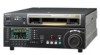
Timecode input/output Audio monitor signal output
 |
View all Sony HDWD1800 manuals
Add to My Manuals
Save this manual to your list of manuals |
Page 26 highlights
Chapter 2 Location and Function of Parts e RS232C (serial interface) connector (D-sub 9-pin) Use this for monitoring and diagnosis of the state of this unit from an external computer, using the ISR (Interactive Status Reporting) function. HDV IN (OPTION) connector (6-pin, conforming to IEEE1394) Use an i.LINK cable to connect this unit to an HDV unit (HVR-1500, HVR-M25, HVR-M15, HVR-Z1, HVR-A1, HDR-FX1, HDR-FX7 or HDR-HC3) recommended by Sony. This connector can be used only when an optional HKDW-105 i.LINK (HDV) Input Board is installed. Notes • If video or audio signals from an external device connected to the HDV input connector fail to be output, disconnect the i.LINK cable and connect it again, pushing it straight in. • Before connecting or disconnecting an i.LINK cable between this unit and a device with a 6-pin i.LINK connector, power off the device and disconnect its power cord from the electrical outlet. If the i.LINK cable is connected or disconnected with the device's power plug still connected, high voltage (8 to 40 V) from the device's i.LINK connector can flow into this unit, possibly damaging the unit. • When connecting this unit to a device with a 6-pin i.LINK connector, connect to the 6-pin i.LINK connector of the other device first. 8 Audio monitor signal output section MONITOR OUTPUT R L 1 MONITOR OUTPUT R connector 2 MONITOR OUTPUT L connector a MONITOR OUTPUT R (right channel) connector (XLR 3-pin, male) This outputs the audio signals whose output destination was set to "R" with the audio monitor signal selection buttons in the audio control section. If multiple tracks have been set to "R", the signals of those tracks are mixed for output. b MONITOR OUTPUT L (left channel) connector (XLR 3-pin, male) This outputs the audio signals whose output destination was set to "L" with the audio monitor signal selection buttons in the audio control section. If multiple tracks have been set to "L", the signals of those tracks are mixed for output. 7 Timecode input/output section TIME CODE IN OUT 1 TIME CODE IN connector 2 TIME CODE OUT connector a TIME CODE IN connector (XLR 3-pin, female) To record timecode from an external device, input a timecode signal from the timecode output connector of the external device. b TIME CODE OUT connector (XLR 3-pin, male) This outputs a timecode according to the operating state of the unit, as follows: • During playback: the playback timecode By setting setup menu item 606, you can also output the timecode from the internal timecode generator locked to the playback timecode. • During recording: the timecode generated by the internal timecode generator or the timecode input to the TIME CODE IN connector. 26 2-2 Connector Panel
-
 1
1 -
2
-
3
-
4
-
5
-
6
-
7
-
8
-
9
-
10
-
11
-
12
-
13
-
14
-
15
-
16
-
17
-
18
-
19
-
20
-
 21
21 -
 22
22 -
 23
23 -
 24
24 -
 25
25 -
 26
26 -
 27
27 -
 28
28 -
 29
29 -
 30
30 -
 31
31 -
32
-
33
-
34
-
35
-
36
-
37
-
38
-
39
-
40
-
41
-
42
-
43
-
44
-
45
-
46
-
47
-
48
-
49
-
50
-
51
-
52
-
53
-
54
-
55
-
56
-
57
-
58
-
59
-
60
-
61
-
62
-
63
-
64
-
65
-
66
-
67
-
68
-
69
-
70
-
71
-
72
-
73
-
74
-
75
-
76
-
77
-
78
-
79
-
80
-
81
-
82
-
83
-
84
-
85
-
86
-
87
-
88
-
89
-
90
-
91
-
92
-
93
-
94
-
95
-
96
-
97
-
98
-
99
-
100
-
101
-
102
-
103
-
104
-
105
-
106
-
107
-
108
-
109
-
110
-
111
-
112
-
113
-
114
-
115
-
116
-
117
-
118
-
119
-
120
-
121
 |
 |
