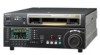
Sony HDWD1800 Operation Manual - Page 19
Audio level control knobs
 |
View all Sony HDWD1800 manuals
Add to My Manuals
Save this manual to your list of manuals |
Page 19 highlights
Chapter 2 Location and Function of Parts 1 Audio level meter block 2 2 System information 3 Information relating to timecode INT-VITC 59.94 SDI 1080 2F ASM LTC DF VITC LTC R-CTRL HD 12:34:47:12 COND R-RUN T O T L : 0 1 1 m i n 4 Time data information 3 Information relating to timecode 1 Audio level meter block 2 For details on audio level indication, see 4 Audio level meter block 2 on page 17. 2 System information For details on indication of the following items, see 1 System information on page 14. • System frequency • Video input signal • Output line information • Capstan lock indication • Edit state indication 3 Information relating to timecode For details on indication of the following items, see 6 Information relating to timecode on page 18. • Time data title • DF status • VITC/LTC status • VTR control mode • TCG mode • TCG RUN mode 4 Time data information For details on indication of the following items, see 5 Time data information on page 17. • Time data display • Tape load mark • Channel condition • Ancillary message display c Menu page selection buttons These buttons select function menu pages to display on the LCD. • P1: HOME button This button selects the HOME function menu page. The HOME page allows you to make settings for basic VTR and editing operations. • P2: TC button This button selects the TC (timecode) function menu page. The TC page allows you to change between LTC and VITC, change between DF and NDF, and make settings for the timecode indications on an external monitor. • P3: VID PROC button This button selects the VID PROC (video processor) function menu page. The VIDEO page allows you to make settings for items relating to video. • P4: AUD INP button This button selects the AUD INP (audio input) function menu page. The AUDIO page allows you to make settings for items relating to audio. • P5: PAGE DOWN button Each time this button is pressed, the function menu page changes in the order P01 t P02 t P03 t P04 t P05 t P06 t P07 t P08 t P01 ... When this button is pressed with the SHIFT/ENTRY button held down, the function menu page changes in the reverse order. d DISPLAY button This button switches the display mode to function display mode, video display mode, or function & video display mode. The mode changes each time the button is pressed. e SHIFT/ENTRY button This button is used to enter an edit point. f ALT(alternative)/DELETE button This button is used to delete an edit point. 2 Audio level control knobs 1 REC knobs REC CH1 PB CH2 CH3 CH4 REC CUE PB 2 PB knobs a REC (audio recording level control) knobs These individually adjust the recording levels on channels 1 to 4, and cue audio. Enter E-E mode, press to protrude the control knobs and adjust the recording level while monitoring the audio level indication in audio level meter block 2. When the knobs are pushed in, the recording levels return to the preset levels and cannot be adjusted. 19 2-1 Control Panels
-
 1
1 -
2
-
3
-
4
-
5
-
6
-
7
-
8
-
9
-
10
-
11
-
12
-
13
-
 14
14 -
 15
15 -
 16
16 -
 17
17 -
 18
18 -
 19
19 -
 20
20 -
 21
21 -
 22
22 -
 23
23 -
 24
24 -
25
-
26
-
27
-
28
-
29
-
30
-
31
-
32
-
33
-
34
-
35
-
36
-
37
-
38
-
39
-
40
-
41
-
42
-
43
-
44
-
45
-
46
-
47
-
48
-
49
-
50
-
51
-
52
-
53
-
54
-
55
-
56
-
57
-
58
-
59
-
60
-
61
-
62
-
63
-
64
-
65
-
66
-
67
-
68
-
69
-
70
-
71
-
72
-
73
-
74
-
75
-
76
-
77
-
78
-
79
-
80
-
81
-
82
-
83
-
84
-
85
-
86
-
87
-
88
-
89
-
90
-
91
-
92
-
93
-
94
-
95
-
96
-
97
-
98
-
99
-
100
-
101
-
102
-
103
-
104
-
105
-
106
-
107
-
108
-
109
-
110
-
111
-
112
-
113
-
114
-
115
-
116
-
117
-
118
-
119
-
120
-
121
 |
 |
