3Com 2928 User Guide
3Com 2928 - Baseline Plus Switch PWR Manual
 |
UPC - 662705557113
View all 3Com 2928 manuals
Add to My Manuals
Save this manual to your list of manuals |
3Com 2928 manual content summary:
- 3Com 2928 | User Guide - Page 1
3Com Baseline Switch 2900 Family User Guide Baseline Switch 2920-SFP Plus Baseline Switch 2928-SFP Plus Baseline Switch 2952-SFP Plus Baseline Switch 2928-PWR Plus Baseline Switch 2928-HPWR Plus Manual Version: 6W102-20090810 www.3com.com 3Com Corporation 350 Campus Drive, Marlborough, MA, USA 01752 - 3Com 2928 | User Guide - Page 2
in 3Com's standard commercial license for the Software. Technical data is provided User Guide. Unless otherwise indicated, 3Com End of Life Statement 3Com processes allow for the recovery, reclamation and safe disposal of all end-of-life electronic components. Regulated Materials Statement 3Com - 3Com 2928 | User Guide - Page 3
file to be used at the next startup from the host of the current user to the device. Save the current configuration to the configuration file to be used at the next startup. Restore the factory default settings. Configure to upload upgrade file from local host, and upgrade the system software - 3Com 2928 | User Guide - Page 4
Routing 31 DHCP 32 Service Management 33 Diagnostic Tools 34 ARP 35 802.1X 36 AAA 37 RADIUS 38 User 39 PKI 40 Port Isolation Group 41 Authorized IP 42 ACL-QoS 43 PoE Contents Configure RMON, and dissplay, create, modify, and clear RMON statistics. Display and configure the energy saving settings of - 3Com 2928 | User Guide - Page 5
Conventions The manual uses the following conventions: Command conventions Convention Boldface italic [ ] { x | y | ... } [ x | y | ... ] { x | y | ... } * [ x | y | ... ] * & # Description The keywords of a command line are in Boldface. Command arguments are in italic. Items (keywords or - 3Com 2928 | User Guide - Page 6
In addition to this manual, each 3com Baseline Switch 2900 documentation set includes the following: Manual Description 3Com Baseline Switch 2900 Family This guide provides all the information you need to install Getting Started Guide and use the 3Com Baseline Switch 2900 Family. Obtaining - 3Com 2928 | User Guide - Page 7
2-13 3 Configuration Through the Command Line Interface 3-1 Getting Started with the Command Line Interface 3-1 Setting Up the Configuration Environment 3-1 Setting Terminal Parameters 3-2 Logging In to the CLI 3-6 CLI Commands 3-6 initialize 3-6 ipsetup 3-7 password 3-8 ping 3-8 quit - 3Com 2928 | User Guide - Page 8
Overview The 3Com baseline switch 2900 family can be configured through the command line interface (CLI), web interface, and SNMP/MIB. These configuration methods are suitable for different application scenarios. z The web interface supports all switch 2900 series configurations. z The CLI provides - 3Com 2928 | User Guide - Page 9
Information needed at login Username Password IP address of the device (VLAN-interface 1) Default value admin None Default IP address of the device, depending on the status of the network where the device resides. 1) The device is not connected to the network, or no DHCP server exists in the - 3Com 2928 | User Guide - Page 10
will dynamically obtain its default IP address through the DHCP server. You can log in to the device through the console port, and execute the summary command to view the information of its default IP address. summary Select menu option: IP Method: IP address: Summary DHCP 10.153.96.86 - 3Com 2928 | User Guide - Page 11
you can select Device > Users from the navigation tree, create a new user, and select Wizard or Network > VLAN interface to configure the IP address of the VLAN interface acting as the management interface. For detailed configuration, refer to the corresponding configuration manuals of these modules - 3Com 2928 | User Guide - Page 12
can only access the device data but cannot configure the device. z Configure: Users of this level can access device data and configure the device, but they cannot upgrade the host software, add/delete/modify users, or back up/restore configuration files. z Management: Users of this level can perform - 3Com 2928 | User Guide - Page 13
2-2 Description of Web-based NM functions Function menu Description User level Wizard IP Setup Perform quick configuration of the device. Management Setup Display global settings and port settings of a stack. Configure Configure global parameters and stack ports. Management IRF Topology - 3Com 2928 | User Guide - Page 14
User level Save Save the current configuration to the configuration file to be used at the next startup. Configure Initialize Restore the factory default settings. Configure File Manage ment File Manage files on the device, such as displaying the Manageme file list, downloading - 3Com 2928 | User Guide - Page 15
VLAN interfaces by address type. Configure Monitor VLAN Interface Create Modify Create VLAN interfaces and configure IP addresses for them. Modify the IP addresses and status of VLAN interfaces. Configure Configure Remove Remove VLAN interfaces. Configure Voice VLAN Summary Setup Port Setup - 3Com 2928 | User Guide - Page 16
VLAN. Configure MAC MAC Display MAC address information. Create and remove MAC addresses. Monitor Configure Setup Display and configure MAC address aging time. Configure Region Display information about MST regions. Modify MST regions. Monitor Configure MSTP Global Port Summary Set - 3Com 2928 | User Guide - Page 17
snooping, and configure DHCP snooping trusted and untrusted ports. Configure Service Service Displays the states of services: enabled or disabled. Enable/disable services, and set related parameters. Configure Management Diagnost ic Tools Ping Trace Route Ping an IPv4 address. Perform trace - 3Com 2928 | User Guide - Page 18
IP. Management Time Range Summary Create Remove Display time range configuration information. Create a time range. Delete a time range. Monitor Configure Configure Summary Display IPv4 ACL configuration information. Monitor Create Create an IPv4 ACL. Configure QoS ACL IPv4 Basic Setup - 3Com 2928 | User Guide - Page 19
traffic behavior Configure Configure Remove Delete a traffic behavior. Configure Summary Display QoS policy configuration information. Monitor QoS Policy Create Setup Create a QoS policy. Configure Configure the classifier-behavior associations for a QoS policy. Configure Remove Delete - 3Com 2928 | User Guide - Page 20
Figure 2-5. You can select Match case and whole word, that is, the item to be searched must completely match the keyword, or you can Restore button Click the button to restore all the items in the current configuration page to the system default. Expand button As shown in Figure 2-6, click the plus - 3Com 2928 | User Guide - Page 21
selected. Figure 2-8 Sort display Configuration Guidelines z The Web-based console supports Microsoft Internet Explorer 6.0 SP2 and higher, but it does not support the Back, Next, Refresh the Web interface. To avoid this problem, it is recommended to turn off the Windows firewall before login. 2-13 - 3Com 2928 | User Guide - Page 22
z If the software version of the device changes, when you log in to the device through the Web interface, you are recommended to delete the temporary Internet files of IE; otherwise, the Web page content may not be displayed correctly. 2-14 - 3Com 2928 | User Guide - Page 23
the Command Line Interface As a supplementary to the web interface, the CLI provides some configuration commands to facilitate your operation. For example, if you forget the IP address of VLAN-interface 1 and cannot log in to the device through the Web interface, you can connect the console port - 3Com 2928 | User Guide - Page 24
PC. Step3 Connect the RJ-45 connector of the console cable to the console port of the switch. (as shown below) Figure 3-2 Network diagram for configuration environment setup Console port Console cable Serial port Pay attention to the mark on the console port and be sure to plug the connector to - 3Com 2928 | User Guide - Page 25
HyperTerminal Help documentation in Help and Support Center on the PC running the Windows operating system. In the following configuration procedure, Windows XP HyperTerminal is used to communicate with the switch. 1) Start the PC and run the terminal emulation program. 2) Set terminal parameters - 3Com 2928 | User Guide - Page 26
OK after selecting a serial port. The following dialog box appears. Set Bits per second to 38400, Data bits to 8, Parity to None, Stop bits to 1, and Flow control to None. Figure 3-5 Set the serial port parameters Step4 Click OK after setting the serial port parameters and the system enters the - 3Com 2928 | User Guide - Page 27
Figure 3-6 HyperTerminal window Step5 Click Properties in the HyperTerminal window to enter the Switch Properties dialog box. Click the Settings tab, set the emulation to VT100, and then click OK. Figure 3-7 Set terminal emulation in Switch Properties dialog box 3-5 - 3Com 2928 | User Guide - Page 28
a list of CLI commands on the device ? Reboot the device and run the default configuration initialize Specify VLAN-interface 1 to obtain an IP address through DHCP or manual configuration ipsetup { dhcp | ip address ip-address { mask | mask-length } [ default-gateway ip-address ] } Modify the - 3Com 2928 | User Guide - Page 29
configured, the command not only assigns an IP address to the interface, but also specifies a default route for the device. Description Use the ipsetup dhcp command to specify VLAN-interface 1 to obtain an IP address through DHCP. Use the ipsetup ip address ip-address { mask | mask-length } command - 3Com 2928 | User Guide - Page 30
for user: admin Old password: *** Enter new password: ** Retype password: ** The password has been successfully changed. ping Syntax ping host Parameters host: Destination IP address (in dotted decimal notation), URL, or host name (a string of 1 to 20 characters). Description Use the ping command to - 3Com 2928 | User Guide - Page 31
that IP address 1.1.2.2 3Com Corporation User interface aux0 is available. Please press ENTER. reboot Syntax reboot Parameters None Description Use the reboot command to reboot the device and run the main configuration file. Note that: z Use the command with caution because reboot results in service - 3Com 2928 | User Guide - Page 32
menu option: Summary IP Method: IP address: Subnet mask: DHCP 10.153.96.86 255.255.255.0 Default gateway: 0.0.0.0 Current boot app is: flash:/2900_release.bin Next main boot app is: NULL Next backup boot app is: NULL 3Com Corporation 3Com Baseline Switch 2928-PWR Plus Software Version 5.20 - 3Com 2928 | User Guide - Page 33
minutes 3Com Baseline Switch 2928-PWR Plus 128M bytes DRAM 128M bytes Nand Flash Memory Config Register points to Nand Flash Hardware Version is REV.B CPLD Version is 001 Bootrom Version is 112 [SubSlot 0] 24GE+4SFP+POE Hardware Version is REV.B upgrade Syntax upgrade server-address source-filename - 3Com 2928 | User Guide - Page 34
(Omitted) 2) Perform the following configurations on the switch. # Configure the IP address of VLAN-interface 1 of the switch as 192.168.1.2/24, and specify the default gateway as 192.168.1.1. ipsetup ip-address 192.168.1.2 24 default-gateway 192.168.1.1 # Download the host software package - 3Com 2928 | User Guide - Page 35
File downloaded successfully. The specified file will be used as the boot file at the next reboot. # Reboot the switch. reboot After getting the new application file, reboot the switch to have the upgraded application take effect. 3-13 - 3Com 2928 | User Guide - Page 36
Table of Contents 1 Configuration Wizard 1-1 Overview 1-1 Basic Service Setup 1-1 Entering the Configuration Wizard Homepage 1-1 Configuring System Parameters 1-1 Configuring Management IP Address 1-3 Finishing Configuration Wizard 1-4 i - 3Com 2928 | User Guide - Page 37
Wizard Overview The configuration wizard guides you through the basic service setup, including the system name, system location, contact information, and management IP address (IP address of the VLAN interface). Basic Service Setup Entering the Configuration Wizard Homepage From the navigation - 3Com 2928 | User Guide - Page 38
page you enter by selecting Device > SNMP. For details, refer to SNMP Configuration. Set the contact information for users to get in touch with the device vendor for help. You can also set the contact information in the setup page you enter by selecting Device > SNMP. For details, refer to SNMP - 3Com 2928 | User Guide - Page 39
the connection to the device. Use the new management IP address to re-log in to the system. A management IP address is the IP address of a VLAN interface, which can be used to access the device. You can also set configure a VLAN interface and its IP address in the page you enter by selecting Network - 3Com 2928 | User Guide - Page 40
length. Support for IPv4 obtaining methods depends on the device model. IPv4 address Specify an IPv4 address and the mask length for the VLAN interface. MaskLen These two text boxes are configurable if Manual is selected. Finishing Configuration Wizard After finishing the management IP address - 3Com 2928 | User Guide - Page 41
Figure 1-4 Configuration finishes The page displays your configurations. Review the configurations and if you want to modify the settings click Back to go back to the page. Click Finish to confirm your settings and the system performs the configurations. 1-5 - 3Com 2928 | User Guide - Page 42
of Contents 1 IRF 1-1 IRF Overview 1-1 Introduction to Stack 1-1 Establishing a Stack 1-1 Configuring an IRF Stack 1-2 Configuration Task List 1-2 Configuring Global Parameters of a Stack 1-3 Configuring Stack Ports 1-4 Displaying Topology Summary of a Stack 1-4 Displaying Device Summary of - 3Com 2928 | User Guide - Page 43
set of network devices. Administrators can group multiple network devices into a stack and manage them as a whole. Therefore, stack management can help a Stack An administrator can establish a stack as follows: z Configure a private IP address pool for a stack and create the stack on the network - 3Com 2928 | User Guide - Page 44
stack. By default, no IP address pool is configured for a stack and no stack is established. Configuring Stack Ports Required Configure the ports of ensure that the username, password, and access right you used to log on to the master device are the same with those configured on the slave device; - 3Com 2928 | User Guide - Page 45
Configuring Global Parameters of a Stack Select IRF from the navigation tree to enter the page shown in Figure 1-2. You can configure global parameters of a stack in the Global Settings area. Figure 1-2 Set up Table 1-2 describes configuration items of global parameters. 1-3 - 3Com 2928 | User Guide - Page 46
you configure a private IP address pool for a stack, the number of IP addresses in the address pool needs to be equal to or greater than the number of devices to be added to the stack. Otherwise, some devices may not be able to join the stack automatically for lack of private IP addresses. Enable - 3Com 2928 | User Guide - Page 47
of the device in the stack: master or slave. Return to Stack configuration task list. Displaying Device Summary of a Stack Select IRF from the device. Figure 1-4 Device summary (the master device) Return to Stack configuration task list. Logging Into a Slave Device From the Master Select IRF - 3Com 2928 | User Guide - Page 48
Slave device SwitchD: Slave device Configuration procedure 1) Configure the master device # Configure global parameters for the stack on Switch A. z Select IRF from the navigation tree of Switch A to enter the page of the Setup tab, and then perform the following configurations, as shown in Figure - 3Com 2928 | User Guide - Page 49
box of Private Net IP. z Type 255.255.255.0 in the text box of Mask. z Select Enable from the Build Stack drop-down list. z Click Apply. Now, switch A becomes the master device. # Configure a stack port on Switch A. z On the page of the Setup tab, perform the following configurations, as shown in - 3Com 2928 | User Guide - Page 50
port on Switch A z In the Port Settings area, select the check box before GigabitEthernet1/0/1. z Click Enable. 2) Configure the slave devices # On Switch B, configure local ports GigabitEthernet 1/0/2 connecting with switch A, GigabitEthernet 1/0/1 connecting with Switch C, and GigabitEthernet - 3Com 2928 | User Guide - Page 51
Configure stack ports on Switch B z In the Port Settings area, select the check boxes before GigabitEthernet1/0/1, GigabitEthernet1/0/2, and GigabitEthernet1/0/3. z Click Enable. Now, switch B becomes a slave device. # On Switch C, configure local port GigabitEthernet 1/0/1 connecting with Switch - 3Com 2928 | User Guide - Page 52
Settings area, select the check box before GigabitEthernet1/0/1. z Click Enable. Now, Switch C becomes a slave device. # On Switch D, configure local port GigabitEthernet 1/0/1 connecting with Switch B as a stack port. z Select IRF from the navigation tree of Switch D to enter the page of the Setup - 3Com 2928 | User Guide - Page 53
an IRF stack, note that: 1) If a device is already configured as the master device of a stack, you are not allowed to modify the private IP address pool on the device. 2) If a device is already configured as a slave device of a stack, the Global Settings area on the slave device is grayed out. 1-11 - 3Com 2928 | User Guide - Page 54
Table of Contents 1 Summary 1-1 Overview 1-1 Displaying Device Summary 1-1 Displaying System Information 1-1 Displaying Device Information 1-2 i - 3Com 2928 | User Guide - Page 55
summary module helps you understand the to the Web interface, the System Information page appears by default, as shown in Figure 1-1. Figure 1-1 System information Select system information at the specified interval. z If you select Manual, the system refreshes the information only when you click the - 3Com 2928 | User Guide - Page 56
version, and running time. The running time displays how long the device is up since the last boot. You can configure the device location and contact information on the Setup page you enter by selecting Device > SNMP. System resource state The System Resource State displays the most current CPU - 3Com 2928 | User Guide - Page 57
Figure 1-2 Device information Select from the Refresh Period drop-down list: z If you select a certain period, the system refreshes the information at the specified interval. z If you select Manual, the system refreshes the information only when you click the Refresh button. 1-3 - 3Com 2928 | User Guide - Page 58
Table of Contents 1 Device Basic Information Configuration 1-1 Overview 1-1 Configuring Device Basic Information 1-1 Configuring System Name 1-1 Configuring Idle Timeout Period 1-1 i - 3Com 2928 | User Guide - Page 59
on the top of the navigation bar. z Set the idle timeout period for a logged-in user. That is, the system will log an idle user off the Web for security purpose after the configured period. Configuring Device Basic Information Configuring System Name Select Device > Basic from the navigation - 3Com 2928 | User Guide - Page 60
Figure 1-2 Configuring idle timeout period Table 1-2 describes the idle timeout period configuration item. Table 1-2 Idle timeout period configuration item Item Idle timeout Description Set the idle timeout period for a logged-in user. 1-2 - 3Com 2928 | User Guide - Page 61
Table of Contents 1 System Time Configuration 1-1 Overview 1-1 Configuring System Time 1-1 System Time Configuration Example 1-2 Configuration Guidelines 1-3 i - 3Com 2928 | User Guide - Page 62
Overview The system time module allows you to display and set the device system time on the Web interface. The device supports setting system time through manual configuration and automatic synchronization of NTP server time. An administrator can by no means keep time synchronized among - 3Com 2928 | User Guide - Page 63
1-1 System time configuration items Item Description Manual Select to manually configure the system time, including the setting of Year, Month, Day, Hour, Minute, and Second. Source Interface Set the source interface for an NTP message. If you do not want the IP address of a certain interface - 3Com 2928 | User Guide - Page 64
the reference clock, with the stratum of 2. Enable NTP authentication, set the key ID to 24, and specify the created authentication key aNiceKey is a trusted key. (Configuration omitted.) 2) Configure Switch B # Configure Device A as the NTP server of Switch B. z Select System > System Time from the - 3Com 2928 | User Guide - Page 65
client will not synchronize its clock to the server's. z The synchronization process takes a period of time. Therefore, the clock status may be unsynchronized after your configuration. In this case, you can click Refresh to view the clock status and system time later on. 1-4 - 3Com 2928 | User Guide - Page 66
Table of Contents 1 Log Management 1-1 Overview 1-1 Configuring Log Management 1-1 Configuration Task List 1-1 Setting Syslog Related Parameters 1-1 Displaying Syslog 1-2 Setting Loghost 1-4 i - 3Com 2928 | User Guide - Page 67
network problems and security problems. System logs can be stored in the log buffer, or sent to the loghost. Configuring Log Management Configuration Task List Perform the tasks in Table 1-1 to configure log management. Table 1-1 Log management configuration task list Task Setting Syslog - 3Com 2928 | User Guide - Page 68
. Table 1-2 Syslog configuration items Item Log Buffer Size Refresh Period Description Set the number of logs that can be stored in the log buffer. Set the refresh period on the log information displayed on the Web interface. You can select manual refresh or automatic refresh: z Manual: You need - 3Com 2928 | User Guide - Page 69
Figure 1-2 Display syslog Table 1-3 describes the syslog display items. Table 1-3 Syslog display items Item Time/Date Source Level Digest Description Description Displays the time/date when system logs are generated. Displays the module that generates system logs. Displays the severity level of - 3Com 2928 | User Guide - Page 70
tree, and click the Loghost tab to enter the loghost configuration page, as shown in Figure 1-3. Figure 1-3 Set loghost Table 1-5 describes the loghost configuration item. Table 1-5 Loghost configuration item Item Loghost IP Description IP address of the loghost. z You can specify up to four - 3Com 2928 | User Guide - Page 71
Table of Contents 1 Configuration Management 1-1 Back Up Configuration 1-1 Restore Configuration 1-1 Save Configuration 1-2 Initialize 1-3 i - 3Com 2928 | User Guide - Page 72
button in this figure, a file download dialog box appears. You can select to view the .xml file or to save the file locally. The switch uses both .cfg and .xml configuration files to save different types of configurations. When backing up or restoring the configuration file, you are recommended to - 3Com 2928 | User Guide - Page 73
Figure 1-3 Save configuration confirmation Click the Save Current Settings button to save the current configuration to the configuration file. z Saving the configuration takes a period of time. z The system does not support the operation of saving configuration of two or more consecutive users. If - 3Com 2928 | User Guide - Page 74
. Select Device > Configuration from the navigation tree, and then click the Initialize tab to enter the initialize confirmation page as shown in Figure 1-4. Figure 1-4 Initialize confirmation dialog box Click the Restore Factory-Default Settings button to restore the system to factory defaults. 1-3 - 3Com 2928 | User Guide - Page 75
Table of Contents 1 Device Maintenance 1-1 Software Upgrade 1-1 Device Reboot 1-2 Electronic Label 1-3 Diagnostic Information 1-3 i - 3Com 2928 | User Guide - Page 76
Software upgrade allows you to obtain a target application file from the current host and set the file as the main boot file or backup boot file to be used at Maintenance from the navigation tree to enter the software upgrade configuration page, as shown in Figure 1-1. Figure 1-1 Software upgrade - 3Com 2928 | User Guide - Page 77
device to make the upgraded software take effect after the application file is uploaded. Device Reboot Before rebooting the device, save the configuration; otherwise, all unsaved configuration will be lost after device reboot. After the device reboots, you need to re-log in to the Web interface - 3Com 2928 | User Guide - Page 78
current configuration and the saved configuration are inconsistent, and the device will not be rebooted. In this case, you need to save the current configuration manually before save the running statistics of multiple functional modules to a file named default.diag, and then you can locate problems - 3Com 2928 | User Guide - Page 79
information file is created Click Click to Download, and the File Download dialog box appears. You can select to open this file or save this file to the local host. z > File Management, or downloading this file to the local host. For the details, refer to File Management Configuration. 1-4 - 3Com 2928 | User Guide - Page 80
Table of Contents 1 File Management 1-1 Overview 1-1 File Management Configuration 1-1 Displaying File List 1-1 Downloading a File 1-1 Uploading a File 1-2 Removing a File 1-2 i - 3Com 2928 | User Guide - Page 81
saves useful files (such as host software, configuration file) into the storage device, and the system provides the file management function for the users in the format of path + filename) saved on the disk and their sizes. Figure 1-1 File management Downloading a File Select Device > File Management - 3Com 2928 | User Guide - Page 82
dialog box appears. You can select to open the file or to save the file locally. You can download only one file at one time. Uploading a File Select Device > File Management from the navigation tree to enter the file management page, as shown in - 3Com 2928 | User Guide - Page 83
Table of Contents 1 Port Management Configuration 1-1 Overview 1-1 Configuring a Port 1-1 Setting Operation Parameters for a Port 1-1 Viewing the Operation Parameters of a Port 1-5 Port Management Configuration Example 1-6 i - 3Com 2928 | User Guide - Page 84
, duplex mode, link type, PVID, MDI mode, flow control settings, MAC learning limit, and storm suppression ratios. Configuring a Port Setting Operation Parameters for a Port Select Device > Port Management from the navigation tree, and then select the Setup tab on the page that appears to enter the - 3Com 2928 | User Guide - Page 85
SFP optical ports do not support the half option. Set the link type of the current port, which can be access, hybrid, or trunk. For details, refer to VLAN Configuration. To change the link type of a port from trunk to hybrid or vice versa, you must first set its link type to access. Set the default - 3Com 2928 | User Guide - Page 86
mode of at least one end must be set to auto. SFP optical ports do not support this feature. Enable or disable flow control on the port. With flow control enabled at both sides, when traffic congestion occurs on the ingress port, the ingress port will send a Pause frame notifying the egress port to - 3Com 2928 | User Guide - Page 87
to input a number in the box below Selected Ports Do not configure this item if the storm constrain function for unicast traffic is enabled on the port. Otherwise, the suppression result will be unpredictable. To set storm constrain for unicast traffic on a port, select Device > Storm Constrain - 3Com 2928 | User Guide - Page 88
tab is displayed by default. Select the parameter you want to view by clicking the radio button before it to display the setting of this parameter for the chassis front panel, as shown in Figure 1-3. The operation parameter settings of the selected port are displayed on the lower part of the page - 3Com 2928 | User Guide - Page 89
of these servers are all 1000 Mbps. z The switch connects to the external network through GigabitEthernet 1/0/4 whose rate is 1000 Mbps. z To avoid congestion at the egress port, GigabitEthernet 1/0/4, configure the auto-negotiation rate range on GigabitEthernet 1/0/1, GigabitEthernet 1/0/2, and - 3Com 2928 | User Guide - Page 90
Configuration procedure # Set the rate of GigabitEthernet 1/0/4 to 1000 Mbps. z Select Device > Port Management from the navigation tree, click the Setup tab to enter the page shown in Figure 1-5, and make the following configurations: Figure 1-5 Configure to end the operation. # Batch configure the - 3Com 2928 | User Guide - Page 91
Figure 1-6 Batch configure port rate # Display the rate settings of ports. z Click the Summary tab. z Select the Speed option to display the rate information of all ports on the lower part of the page, as shown in Figure 1-7. 1-8 - 3Com 2928 | User Guide - Page 92
Figure 1-7 Display the rate settings of ports 1-9 - 3Com 2928 | User Guide - Page 93
Table of Contents 1 Port Mirroring Configuration 1-1 Introduction to Port Mirroring 1-1 Implementing Port Mirroring 1-1 Configuring Port Mirroring 1-1 Configuration Task List 1-1 Creating a Mirroring Group 1-2 Configuring Ports for a Mirroring Group 1-3 Configuration Examples 1-4 Local Port - 3Com 2928 | User Guide - Page 94
processes packets Traffic mirrored to Mirroring port Monitor port Mirroring port Monitor port Data monitoring device PC Configuring Port Mirroring Configuration Task List Configuring local port mirroring To configure local port mirroring, you must create a local mirroring group and then specify - 3Com 2928 | User Guide - Page 95
Refer to section Creating a Mirroring Group for details. Required Refer to section Configuring Ports for a Mirroring Group for details. During configuration, you need to select the port type Mirror Port. You can configure multiple mirroring ports for a mirroring group. Required Refer to section - 3Com 2928 | User Guide - Page 96
Mirroring Group ID ID of the mirroring group to be configured The available groups were created previously. Port Type Set the type of the port to be configured Configure ports for a local mirroring group: z Monitor Port: Configures the monitor ports for the local mirroring group. z Mirror Port - 3Com 2928 | User Guide - Page 97
Select port(s) Description Set the direction of the traffic monitored by the monitor port of the mirroring group This configuration item is available when following configuration on Switch C: z Configure GigabitEthernet 1/0/1 and GigabitEthernet 1/0/2 as mirroring ports. z Configure GigabitEthernet - 3Com 2928 | User Guide - Page 98
a local mirroring group z Type in mirroring group ID 1. z Select Local in the Type drop-down list. z Click Apply. # Configure the mirroring ports. Click Modify Port to enter the page for configuring ports for the mirroring group, as shown in Figure 1-6. Figure 1-6 Configure the mirroring ports 1-5 - 3Com 2928 | User Guide - Page 99
progress dialog box appears, as shown in Figure 1-7. Figure 1-7 Configuration progress dialog box z After the configuration process is complete, click Close. # Configure the monitor port. Click Modify Port to enter the page for configuring ports for the mirroring group, as shown in Figure - 3Com 2928 | User Guide - Page 100
Guidelines Pay attention to the following points during local port mirroring configuration: z To ensure operation of your device, do not enable STP, MSTP, or RSTP on the monitor port. z You can configure multiple mirroring ports but only one monitor port for a local mirroring group. 1-7 - 3Com 2928 | User Guide - Page 101
Table of Contents 1 User Management 1-1 Overview 1-1 Users 1-1 Creating a User 1-1 Setting the Super Password 1-2 Switching the User Access Level to the Management Level 1-3 i - 3Com 2928 | User Guide - Page 102
, and access level for an FTP or Telnet user. z Set the super password for switching the current Web user level to the management level. z Switch the current Web user access level to the management level. Users Creating a User Select Device > Users from the navigation tree, and click the Create - 3Com 2928 | User Guide - Page 103
Configure: Users of this level can access data on the device and configure the device, but they cannot upgrade the host software, add/delete/modify users, or back up/restore the application file. z Management: Users of this level can perform any operations on the device. Set the password for a user - 3Com 2928 | User Guide - Page 104
Set the password display mode. z Simple: The password will be saved in the configuration file in plain text. z Cipher: The password will be saved in the configuration file in cipher text. The plaintext password is not safe, and you are recommended to use the ciphertext password. Switching the User - 3Com 2928 | User Guide - Page 105
Figure 1-3 Switch to the management level. 1-4 - 3Com 2928 | User Guide - Page 106
Table of Contents 1 Loopback Test Configuration 1-1 Overview 1-1 Loopback Operation 1-1 Configuration Guidelines 1-2 i - 3Com 2928 | User Guide - Page 107
page, as shown in Figure 1-1. Figure 1-1 Loopback test configuration page Table 1-1 describes the loopback test configuration items. Table 1-1 Loopback test configuration items Item Description Testing type External Internal Sets the loopback test type, which can be External or Internal - 3Com 2928 | User Guide - Page 108
box, as shown in Figure 1-2. Figure 1-2 Loopback test result Configuration Guidelines Note the following when performing a loopback test: z You can test on a port that is manually shut down. z The system does not allow Rate, Duplex, Cable Type and Port Status configuration on a port under a loopback - 3Com 2928 | User Guide - Page 109
Table of Contents 1 VCT 1-1 Overview 1-1 Testing Cable Status 1-1 i - 3Com 2928 | User Guide - Page 110
1 VCT Overview z The optical interface of a SFP port does not support this feature. z A link in the up state goes down and then up automatically if you perform this operation on one of the Ethernet interfaces forming - 3Com 2928 | User Guide - Page 111
Table 1-1 Description on the cable test result Item Description Cable status Status and length of the cable. The status of a cable can be normal, abnormal, abnormal(open), abnormal(short), or failure. z When a cable is normal, the cable length displayed is the total length of the cable. z When a - 3Com 2928 | User Guide - Page 112
Table of Contents 1 Flow Interval Configuration 1-1 Overview 1-1 Monitoring Port Traffic Statistics 1-1 Setting the Traffic Statistics Generating Interval 1-1 Viewing Port Traffic Statistics 1-1 i - 3Com 2928 | User Guide - Page 113
sending rate of a port over the specified interval. Monitoring Port Traffic Statistics Setting the Traffic Statistics Generating Interval Select Device > Flow interval from the navigation bar, and click the Interval Configuration tab to enter the page shown in Figure 1-1. Figure 1-1 The page for - 3Com 2928 | User Guide - Page 114
Figure 1-2 Port traffic statistics 1-2 - 3Com 2928 | User Guide - Page 115
Table of Contents 1 Storm Constrain Configuration 1-1 Overview 1-1 Configuring Storm Constrain 1-1 Setting the Traffic Statistics Generating Interval 1-1 Configuring Storm Constrain 1-2 i - 3Com 2928 | User Guide - Page 116
suppression enabled on a port, do not enable storm constrain for broadcast traffic on the port. The storm suppression function is configured in Device Port Management to configure the port, or cancel the storm constrain setting on the port. Configuring Storm Constrain Setting the Traffic Statistics - 3Com 2928 | User Guide - Page 117
measuring the average traffic sending and receiving rates over a specific interval. z For network stability sake, set the traffic statistics generating interval for the storm constrain function to the default or a greater value. Configuring Storm Constrain Select Device > Storm Constrain from the - 3Com 2928 | User Guide - Page 118
analyzes the data in the next interval. Thus, it is normal that a period longer than one traffic statistics generating interval is waited for a control action to happen if you enable the function while the packet storm is present. Nevertheless, the action will be taken within two intervals. Set the - 3Com 2928 | User Guide - Page 119
trap messages both when an upper threshold is crossed and when the corresponding lower threshold is crossed after that. Select or clear the option to enable or disable the system to output logs both when an upper threshold is crossed and when the corresponding lower threshold is crossed after that - 3Com 2928 | User Guide - Page 120
1 RMON 1-1 RMON Overview 1-1 Working Mechanism 1-1 RMON Groups 1-2 Configuring RMON 1-3 Configuration Task List 1-3 Configuring a Statistics Entry 1-5 Configuring a History Entry 1-6 Configuring an Event Entry 1-7 Configuring an Alarm Entry 1-7 Displaying RMON Statistics Information - 3Com 2928 | User Guide - Page 121
of received packets or total number of oversize packets received. The alarm function enables a managed device to monitor the value of a specified MIB variable, log devices such as routers, switches, and hubs to provide the RMON probe function. Management devices exchange data with RMON agents using - 3Com 2928 | User Guide - Page 122
interfaces are supported) and saves the statistics data includes bandwidth utilization, number of error packets, and total number of packets. A history group collects statistics on packets received on the interface during each period, which can be configured through the command line interface (CLI - 3Com 2928 | User Guide - Page 123
the current interface, and saves the statistics as an instance under the leaf node of the etherHistoryEntry table. When you create an entry, if the value of the specified sampling interval is identical to that of the existing history entry, the system considers their configurations are the same and - 3Com 2928 | User Guide - Page 124
take no action, and log the event and send a trap to the NMS. Configuring an Alarm Entry An entry cannot be created if the values of the specified , the system calculates the information of the interface periodically and saves the information to the etherHistoryEntry table. You can perform this - 3Com 2928 | User Guide - Page 125
a statistics entry. Table 1-5 Statistics entry configuration items Item Interface Name Owner Description Select the name of the interface on which the statistics entry is created. Only one statistics entry can be created on one interface. Set the owner of the statistics entry. Return to - 3Com 2928 | User Guide - Page 126
entry configuration items Item Interface Name Buckets Granted Interval Owner Description Select the name of the interface on which the history entry is created. Set the capacity of the history record list corresponding to this history entry, namely, the maximum number of records that can be saved - 3Com 2928 | User Guide - Page 127
1-6 Add an event entry Table 1-7 describes the items for configuring an event entry. Table 1-7 Event entry configuration items Item Description Owner Event Type Description Set the description for the event. Set the owner of the entry. Set the actions that the system will take when the event is - 3Com 2928 | User Guide - Page 128
1-7 Alarm entry Figure 1-8 Add an alarm entry Figure 1-8 describes the items for configuring an alarm entry. Table 1-8 Alarm entry configuration items Item Description Alarm variable Statics Item Interface Name Set the traffic statistics that will be collected and monitored, see Table 1-9 for - 3Com 2928 | User Guide - Page 129
of the alarm variable is higher than the alarm rising threshold. If the Create Default Event check box is selected, this option is not configurable. Falling Threshold Set the alarm falling threshold. Falling Event Set the action that the system will take when the value of the alarm variable is - 3Com 2928 | User Guide - Page 130
Figure 1-9 RMON statistics information Table 1-9 describes the fields of RMON statistics. Table 1-9 Fields of RMON statistics Item Number of Received Bytes Number of Received Packets Number of Received Broadcasting Packets Number of Received Multicast Packets Number of Received Packets With CRC - 3Com 2928 | User Guide - Page 131
Item Description Number of Received Packets Smaller Than 64 Bytes Total number of undersize packets (shorter than 64 octets) received by the interface, corresponding to the MIB node etherStatsUndersizePkts. Number of Received Packets Larger Than 1518 Bytes Total number of oversize packets ( - 3Com 2928 | User Guide - Page 132
are numbered chronologically when they are saved to the system buffer. Time at which the information is saved Dropped packets during the sampling period etherHistoryFragments. Number of jabbers received during the sampling period (Support for the field depends on the device model.), corresponding to - 3Com 2928 | User Guide - Page 133
as shown in Figure 1-11, which displays log information for all event entries. Figure 1-11 Log Return to Display RMON running status. RMON Configuration Example Network requirements As shown in Figure 1-12, Agent is connected to a remote NMS across the Internet. Create an entry in the RMON Ethernet - 3Com 2928 | User Guide - Page 134
Figure 1-13 Add a statistics entry z Select GigabitEthernet1/0/1 from the Interface Name drop-down box. z Type user1-rmon in the text box of Owner. z Click Apply. # Display RMON statistics for interface Ethernet 1/0/1. z Click the icon corresponding to GigabitEthernet 1/0/1. z You can view the - 3Com 2928 | User Guide - Page 135
Figure 1-14 Display RMON statistics # Create an event to start logging after the event is triggered. z Click the Event tab, click Add, and then perform the following configurations, as shown in Figure 1-15. Figure 1-15 Configure an event group 1-15 - 3Com 2928 | User Guide - Page 136
you can see that the entry index of the new event is 1, as shown in Figure 1-16. Figure 1-16 Display the index of a event entry # Configure an alarm group to sample received bytes on Ethernet 1/0/1. When the received bytes exceed the rising or falling threshold, logging is - 3Com 2928 | User Guide - Page 137
z Select Number of Received Bytes from the Statics Item drop-down box. z Select GigabitEthernet1/0/1 from the Interface Name drop-down box. z Type 10 in the text box of Interval. z Select Delta from the Simple Type drop-down box. z Type 1-rmon in the text box of Owner. z Type 1000 in the text box of - 3Com 2928 | User Guide - Page 138
Table of Contents 1 Energy Saving Configuration 1-1 Overview 1-1 Configuring Energy Saving on a Port 1-1 i - 3Com 2928 | User Guide - Page 139
a port Item Time Range Sun through Sat PoE Disabled Description Set the time period when the port is in the state of energy saving. z Up to five energy saving policies with different time ranges can be configured on a port. z Specify the start time and end time in units of 5 minutes, such as 08:05 - 3Com 2928 | User Guide - Page 140
Shutdown Description Set the port to transmit data at the lowest speed. If you configure the lowest speed limit on a port that does not support 10 Mbps, the configuration cannot take effect. Shut down the port. An energy saving policy can have all the three energy saving schemes configured, of - 3Com 2928 | User Guide - Page 141
Mechanism 1-1 SNMP Protocol Version 1-1 MIB Overview 1-2 SNMP Configuration 1-3 Configuration Task List 1-3 Enabling SNMP 1-4 Configuring an SNMP View 1-5 Configuring an SNMP Community 1-7 Configuring an SNMP Group 1-8 Configuring an SNMP User 1-10 Configuring SNMP Trap Function 1-11 SNMP - 3Com 2928 | User Guide - Page 142
enables network administrators to search and modify information, find and diagnose network problems client software. It offers a user friendly interface, making it easier the agent through this operation. z Set operation: NMS can reconfigure the value Currently, SNMP agents support SNMPv3 and are - 3Com 2928 | User Guide - Page 143
supports more data types such as Counter64; and it provides various error codes, thus being able to distinguish errors in more detail. z SNMPv3 offers an authentication that is implemented with a User-Based Security Model (USM). You can set versions configured on them. You can configure multiple - 3Com 2928 | User Guide - Page 144
short bits of the subtree mask will be set to 1 during subtree mask-OID matching. z If no subtree mask is specified, the default subtree mask (all Fs) will be used for mask-OID matching. SNMP Configuration Configuration Task List As configurations for SNMPv3 differ substantially from those for - 3Com 2928 | User Guide - Page 145
, you need to create the SNMP group to which the user belongs. Configuring SNMP Trap Function Optional Allows you to configure that the agent can send SNMP traps to the NMS, and configure information about the target host of the SNMP traps By default, an agent is allowed to send SNMP traps to the - 3Com 2928 | User Guide - Page 146
engine ID, the user is invalid. Configure the maximum size of an SNMP packet that the agent can receive/send. Set a character string to describe the contact information for system maintenance. If the device is faulty, the maintainer can contact the manufacture factory according to the contact - 3Com 2928 | User Guide - Page 147
enter the page as shown in Figure 1-7. Figure 1-6 Create an SNMP view (1) Figure 1-7 Create an SNMP view (2) Table 1-4 describes the configuration items for creating an SNMP view. After configuring the parameters of a rule, click Add to add the rule into the list box at the lower part of the page - 3Com 2928 | User Guide - Page 148
subtree. Set the subtree mask. If no subtree mask is specified, the default subtree mask (all Fs) will be used for mask-OID matching. Adding rules the view. Return to SNMPv1 or SNMPv2c configuration task list or SNMPv3 configuration task list. Configuring an SNMP Community Select Device > SNMP from - 3Com 2928 | User Guide - Page 149
configuration items for configuring an SNMP community. Table 1-5 Configuration items for configuring an SNMP community Item Community Name Access Right View ACL Description Set the SNMP community name. Configure IP address. Return to SNMPv1 or SNMPv2c configuration task list. Configuring an - 3Com 2928 | User Guide - Page 150
1-11 SNMP group Figure 1-12 Create an SNMP group Table 1-6 describes the configuration items for creating an SNMP group. Table 1-6 Configuration items for creating an SNMP group Item Group Name Security Level Description Set the SNMP group name. Select the security level for the SNMP group. The - 3Com 2928 | User Guide - Page 151
of SNMP packets, that is, you can configure to allow or prohibit SNMP packets with a specific source IP address, so as to restrict the intercommunication between the NMS and the agent. Return to SNMPv3 configuration task list. Configuring an SNMP User Select Device > SNMP from the navigation tree - 3Com 2928 | User Guide - Page 152
Privacy Password Confirm Privacy Password ACL Set the privacy password when the security level is Auth/Priv. The confirm privacy password must be the same with the privacy password. Associate a basic ACL with the user to restrict the source IP address of SNMP packets, that is, you can configure to - 3Com 2928 | User Guide - Page 153
for adding a target host of SNMP traps. Table 1-8 Configuration items for adding a target host Item Destination IP Address Security Name UDP Port Security Model Security Level Description Set the destination IP address. Select the IP address type: IPv4 or IPv6, and then type the corresponding - 3Com 2928 | User Guide - Page 154
receive traps. Figure 1-17 Network diagram for SNMP configuration Configuration procedure 1) Configure Agent # Configuration IP addresses for the interfaces. (Omitted) # Enable SNMP. Select Device > SNMP from the navigation tree, and you will enter the Setup page as shown in Figure 1-18. Figure 1-18 - 3Com 2928 | User Guide - Page 155
the text box. z Click Apply to enter the SNMP rule configuration page, as shown in Figure 1-20. Figure 1-20 Create an SNMP view (2) z Select the Included radio box. z Type the MIB subtree OID interfaces. z Click Add. z Click Apply. A configuration progress dialog box appears, as shown in Figure 1-21 - 3Com 2928 | User Guide - Page 156
text box of Group Name. z Select view1 from the Read View drop-down box. z Select view1 from the Write View drop-down box. z Click Apply. # Configure an SNMP user z Click the User tab and then click Add to enter the page as shown in Figure 1-23. Figure 1-23 Create an SNMP - 3Com 2928 | User Guide - Page 157
as shown in Figure 1-25. Figure 1-25 Add target hosts of SNMP traps z Select the destination IP address type as IPv4. z Type the destination address 1.1.1.2. z Type the user name user1. z Type the UDP port 5000. z Select v3 from the Security Model drop-down box. z Click Apply. 2) Configure NMS. 1-16 - 3Com 2928 | User Guide - Page 158
, privacy mode, privacy password, and so on. Besides, you need to configure the aging time and retry times. After the above configurations, you can configure the device as needed through the NMS. For related configurations, refer to the manual provided for NMS. Configuration verification z After the - 3Com 2928 | User Guide - Page 159
Table of Contents 1 Interface Statistics 1-1 Overview 1-1 Displaying Interface Statistics 1-1 i - 3Com 2928 | User Guide - Page 160
1 Interface Statistics Overview The interface statistics module displays statistics information about the packets received and sent through interfaces. Displaying Interface Statistics Select Device > Interface Statistics from the navigation tree to enter the interface statistics display page, as - 3Com 2928 | User Guide - Page 161
Field OutUcastPkts OutNUcastPkts OutDiscards OutErrors Description Number of unicast packets sent through the interface. Number of non-unicast packets sent through the interface. Number of valid packets discarded in the outbound direction. Number of invalid packets sent through the interface. 1-2 - 3Com 2928 | User Guide - Page 162
Introduction to VLAN 1-1 How VLAN Works 1-1 VLAN Types 1-2 Introduction to Port-Based VLAN 1-3 Configuring a VLAN 1-4 Configuration Task List 1-4 Creating VLANs 1-4 Selecting VLANs 1-5 Modifying a VLAN 1-6 Modifying Ports 1-8 VLAN Configuration Example 1-9 Configuration Guidelines 1-13 - 3Com 2928 | User Guide - Page 163
broadcasts are common on an Ethernet. To address the issue, virtual LAN (VLAN) was introduced. The idea is to break a LAN down into separate VLANs, that is, Layer 2 broadcast domains whereby frames are switched between ports assigned to the same VLAN. VLANs are isolated from each other at Layer - 3Com 2928 | User Guide - Page 164
are encapsulated in canonical format; value 1 indicates that the MAC addresses are encapsulated in non-canonical format. The field is set to 0 by default. z The 12-bit VLAN ID field identifies the VLAN the frame belongs to. The VLAN ID range is 0 to 4095. As 0 and 4095 are reserved by the protocol - 3Com 2928 | User Guide - Page 165
access port can join only one VLAN, its default VLAN is the VLAN to which it belongs and cannot be configured. z Because a trunk or hybrid port can join multiple VLANs, you can configure a default VLAN for the port. A port configured with a default VLAN handles a frame as follows: Port type Access - 3Com 2928 | User Guide - Page 166
the following two approaches to configure a VLAN: z Approach I: modify a VLAN, as shown in Table 1-1. z Approach II: modify a port, as shown in Table 1-2. Table 1-1 VLAN configuration task list (approach I) Task Remarks Creating VLANs Selecting VLANs Modifying a VLAN Required Create one or - 3Com 2928 | User Guide - Page 167
of the page. Set the description string of the selected VLAN. By default, the description string of a VLAN is its VLAN ID, such as VLAN 0001. Return to VLAN configuration task list (approach I). Return to VLAN configuration task list (approach II). Selecting VLANs Select Network > VLAN from the - 3Com 2928 | User Guide - Page 168
one of the two radio buttons: z Display all VLANs: displays all configured VLANs. z Display a subnet of all configured VLANs: type the VLAN ID(s) to be displayed. Return to VLAN configuration task list (approach I). Modifying a VLAN Select Network > VLAN from the navigation tree and click Modify - 3Com 2928 | User Guide - Page 169
Modify Description Modify the description string of the selected VLAN. By default, the description string of a VLAN is its VLAN ID, such as VLAN 0001. Select memb ership type Untagged Tagged Not A Member Select ports to be modified and assigned to this VLAN Set the member type of the port to be - 3Com 2928 | User Guide - Page 170
panel. You can select one or more ports. If aggregation groups are configured on the device, the page displays a list of aggregated ports below the of those VLANs without removing the VLAN tags. z Not A Member: Removes the selected ports from the specified VLANs. Set the IDs of the VLANs to/from - 3Com 2928 | User Guide - Page 171
Network diagram for VLAN configuration Configuration procedure 1) Configure Switch A # Configure GigabitEthernet 1/0/1 as a trunk port and configure VLAN 100 as its default VLAN. Select Device > Port Management from the navigation tree and click Setup to enter the page for setting ports, as shown - 3Com 2928 | User Guide - Page 172
1-9 Configure GigabitEthernet 1/0/1 as a trunk port and its PVID as 100 z Select Trunk in the Link Type drop-down list. z Select the PVID check box, and then type in PVID 100. z Select GigabitEthernet 1/0/1 on the chassis front device panel. z Click Apply. # Create VLAN 2, VLAN 6 through VLAN 50 - 3Com 2928 | User Guide - Page 173
, 100. z Click Apply. # Assign GigabitEthernet 1/0/1 to VLAN 100 as an untagged member. Click Select VLAN to enter the page for selecting VLANs, as shown in Figure 1-11. Figure 1-11 Set a VLAN range z Select the radio button before Display a subnet of all configured VLANs and type 1-100 in the text - 3Com 2928 | User Guide - Page 174
device panel. z Click Apply. A configuration progress dialog box appears, as shown in Figure 1-13. Figure 1-13 Configuration progress dialog box z After the configuration process is complete, click Close. # Assign GigabitEthernet 1/0/1 to VLAN2, and VLAN 6 through VLAN 50 as a tagged member. 1-12 - 3Com 2928 | User Guide - Page 175
, click Close in the dialog box. 2) Configure Switch B Configure Switch B as you configure Switch A. Configuration Guidelines When configuring VLAN, note that: 1) VLAN 1 is the default VLAN, which can be neither created nor removed manually. 2) Some VLANs are reserved for some special purposes. You - 3Com 2928 | User Guide - Page 176
Table of Contents 1 VLAN Interface Configuration 1-1 Overview 1-1 Configuring VLAN Interfaces 1-1 Configuration Task List 1-1 Creating a VLAN Interface 1-1 Modifying a VLAN Interface 1-3 i - 3Com 2928 | User Guide - Page 177
can assign the VLAN interface an IP address and specify it as the gateway of the VLAN to forward the traffic destined for an IP network segment different from that of the VLAN. Configuring VLAN Interfaces Configuration Task List Perform the tasks in Table 1-1 to configure a VLAN interface: Table - 3Com 2928 | User Guide - Page 178
in which the VLAN interface gets an IPv4 address. Allow the VLAN interface to automatically obtain an IP address by selecting the DHCP or BOOTP option, or manually assign the VLAN interface an IP address by selecting the Manual option. Configure an IPv4 address for the VLAN interface. This option - 3Com 2928 | User Guide - Page 179
IP address to re-log in. Select Network > VLAN Interface from the navigation tree and click Modify to enter the page for modifying a VLAN interface, as shown in Figure 1-2. Figure 1-2 The Modify tab Table 1-3 describes the configuration items of modifying a VLAN interface. Table 1-3 Configuration - 3Com 2928 | User Guide - Page 180
the VLAN interface an IP address by selecting the Manual option. Select Up or Down in the Admin Status drop-down list to bring up or shut down the selected VLAN interface. When the VLAN interface fails, you can shut down and then bring up the VLAN interface, which may restore it. By default, a VLAN - 3Com 2928 | User Guide - Page 181
List 1-4 Configuring Voice VLAN Globally 1-5 Configuring Voice VLAN on a Port 1-6 Adding OUI Addresses to the OUI List 1-7 Voice VLAN Configuration Examples 1-8 Configuring Voice VLAN on a Port in Automatic Voice VLAN Assignment Mode 1-8 Configuring a Voice VLAN on a Port in Manual Voice VLAN - 3Com 2928 | User Guide - Page 182
you can configure quality of service (QoS) parameters for the voice traffic, thus improving transmission priority and ensuring voice quality. A device determines whether a received packet is a voice packet by checking its source MAC address. If the source MAC address of a received packet matches an - 3Com 2928 | User Guide - Page 183
traffic Tagged voice traffic Manual mode Untagged voice traffic Access Not supported Not supported Not supported Supported, but you must configure the default VLAN of the port as the voice VLAN. Port link type Trunk Hybrid Supported, but you must ensure that the default VLAN of the port has - 3Com 2928 | User Guide - Page 184
to pass through a voice VLAN-enabled inbound port. When receiving a voice packet, the port forwards it without checking its source MAC address against the OUI addresses configured for the device. If the default VLAN of the port is the voice VLAN and the port works in manual VLAN assignment mode, the - 3Com 2928 | User Guide - Page 185
is automatic, and the voice VLAN function is disabled on a port. Optional The system supports up to 16 OUI addresses. By default, the system is configured with seven OUI addresses, as shown in Table 1-1. Configuring voice VLAN on a port working in manual voice VLAN assignment mode Perform the tasks - 3Com 2928 | User Guide - Page 186
. For details, refer to Port Management Configuration. Configuring Voice VLAN on a Port Adding OUI Addresses to the OUI List Required Configure the voice VLAN assignment mode of a port as manual and enable voice VLAN on the port. By default, the voice VLAN assignment mode of a port is automatic - 3Com 2928 | User Guide - Page 187
items of configuring Voice VLAN for a port Item Voice VLAN port mode Voice VLAN port state Voice VLAN ID Description Set the voice VLAN assignment mode of a port to: z Auto, that is, automatic voice VLAN assignment mode z Manual, that is, manual voice VLAN assignment mode Select Enable or Disable - 3Com 2928 | User Guide - Page 188
not belong to the voice VLAN. Return to Configuring voice VLAN on a port in automatic voice VLAN assignment mode. Return to Configuring voice VLAN on a port working in manual voice VLAN assignment mode. Adding OUI Addresses to the OUI List Select Network > Voice VLAN from the navigation tree and - 3Com 2928 | User Guide - Page 189
z The IP phone connected to hybrid port GigabitEthernet 1/0/1 sends untagged voice traffic. z GigabitEthernet 1/0/1 operates in automatic VLAN assignment mode. Set the voice VLAN aging timer to 30 minutes. z Configure GigabitEthernet 1/0/1 to allow voice packets whose source MAC addresses match the - 3Com 2928 | User Guide - Page 190
Figure 1-5 Create VLAN 2 z Type in VLAN ID 2. z Click Create. # Configure GigabitEthernet 1/0/1 as a hybrid port. z Select Device > Port Management from the navigation tree, and click Setup on the displayed page to enter the page shown in Figure 1-6. 1-9 - 3Com 2928 | User Guide - Page 191
the Link Type dropdown list. z Select GigabitEthernet 1/0/1 from the chassis front panel. z Click Apply. # Configure the voice VLAN function globally. z Select Network > Voice VLAN from the navigation tree and click the Setup tab on the displayed page to enter the page shown in Figure 1-7. Figure - 3Com 2928 | User Guide - Page 192
the voice VLAN security mode is enabled by default) z Set the voice VLAN aging timer to 30 minutes. z Click Apply. # Configure voice VLAN on GigabitEthernet 1/0/1. z Click the Port Setup tab to enter the page shown in Figure 1-8. Figure 1-8 Configure voice VLAN on GigabitEthernet 1/0/1 z Select - 3Com 2928 | User Guide - Page 193
description string test. z Click Apply. Verify the configuration z When the configurations described above are completed, the OUI Summary tab is displayed by default, as shown in Figure 1-10. You can view the information about the newly-added OUI address. Figure 1-10 Current OUI list of the device - 3Com 2928 | User Guide - Page 194
z Configure VLAN 2 as a voice VLAN that carries only voice traffic. z The IP phone connected to hybrid port GigabitEthernet 1/0/1 sends untagged voice traffic. z GigabitEthernet 1/0/1 operates in manual voice VLAN assignment mode and allows voice packets whose source MAC addresses match the - 3Com 2928 | User Guide - Page 195
Figure 1-13 Create VLAN 2 z Type in VLAN ID 2. z Click Create. # Configure GigabitEthernet 1/0/1 as a hybrid port and configure its default VLAN as VLAN 2. z Select Device > Port Management from the navigation tree, and click Setup on the displayed page to enter the page shown in Figure 1-14. 1-14 - 3Com 2928 | User Guide - Page 196
Figure 1-14 Configure GigabitEthernet 1/0/1 as a hybrid port z Select Hybrid from the Link Type dropdown list. z Select the PVID option and type 2 in the text box. z Select GigabitEthernet 1/0/1 from the chassis front panel. z Click Apply. # Assign GigabitEthernet 1/0/1 to VLAN 2 as an untagged - 3Com 2928 | User Guide - Page 197
, as shown in Figure 1-16. Figure 1-16 Configuration progress dialog box z After the configuration process is complete, click Close. # Configure voice VLAN on GigabitEthernet 1/0/1. z Select Network > Voice VLAN from the navigation tree, and click Port Setup on the displayed page to enter the page - 3Com 2928 | User Guide - Page 198
1-17 Configure voice VLAN on GigabitEthernet 1/0/1 z Select Manual in the Voice VLAN port mode drop-down list. z Select Enable in the Voice VLAN port state drop-down list. z Type in voice VLAN ID 2. z Select GigabitEthernet 1/0/1 on the chassis front panel. z Click Apply. # Add OUI addresses to the - 3Com 2928 | User Guide - Page 199
description string test. z Click Apply. Verify the configuration z When the configurations described above are completed, the OUI Summary tab is displayed by default, as shown in Figure 1-19. You can view the information about the newly-added OUI address. Figure 1-19 Current OUI list of the device - 3Com 2928 | User Guide - Page 200
present, only one VLAN is supported and only an existing static VLAN can be configured as the voice VLAN. z If Link Aggregation Control Protocol (LACP) is enabled on a port, the voice VLAN function cannot be enabled on it. z After you assign a port working in manual voice VLAN assignment mode to the - 3Com 2928 | User Guide - Page 201
Table of Contents 1 MAC Address Configuration 1-1 Overview 1-1 Configuring MAC Addresses 1-2 Configuring a MAC Address Entry 1-2 Setting the Aging Time of MAC Address Entries 1-4 MAC Address Configuration Example 1-5 i - 3Com 2928 | User Guide - Page 202
for frame forwarding. Each entry in this table indicates the MAC address of a connected device, to which interface this device is connected and to which VLAN the interface belongs. A MAC address table consists of two types of entries: static and dynamic. Static entries are manually configured and - 3Com 2928 | User Guide - Page 203
entry matches the destination MAC address, the device broadcasts the frame to all the ports except the receiving port. Figure 1-1 MAC address table of the device Configuring MAC Addresses MAC addresses configuration includes the configuring and displaying of MAC address entries, and the setting of - 3Com 2928 | User Guide - Page 204
Figure 1-2 The MAC tab Figure 1-3 Create a MAC address entry Table 1-1 shows the detailed configuration of creating a MAC address entry. 1-3 - 3Com 2928 | User Guide - Page 205
MAC address entries manually configured by the users z Blackhole: indicates blackhole MAC address entries z Learned: indicates dynamic MAC address entries learned by the device z Other: indicates types other than the ones mentioned above Set the ID of the VLAN to which the MAC address belongs Set - 3Com 2928 | User Guide - Page 206
table management function of the Web-based NMS. It is required to add a static MAC address 00e0-fc35-dc71 under GigabitEthernet 1/0/1 in VLAN 1. Configuration procedure # Create a static MAC address entry. Select Network > MAC from the navigation tree to enter the MAC tab, and then click Add, as - 3Com 2928 | User Guide - Page 207
MSTP 1-10 How MSTP Works 1-14 Implementation of MSTP on Devices 1-14 Protocols and Standards 1-15 Configuring MSTP 1-15 Configuration Task List 1-15 Configuring an MST Region 1-15 Configuring MSTP Globally 1-16 Configuring MSTP on a Port 1-19 Displaying MSTP Information of a Port 1-21 MSTP - 3Com 2928 | User Guide - Page 208
tree protocols derived from that protocol. Protocol Packets of STP STP uses bridge protocol data units (BPDUs), also known as configuration messages, as its protocol packets. STP-enabled network devices exchange BPDUs to establish a spanning tree. BPDUs contain sufficient information for the - 3Com 2928 | User Guide - Page 209
Root port On a non-root bridge, the port nearest to the root bridge is called the root port. The root port is responsible for communication with the root bridge. Each non-root bridge has one and only one root port. The root bridge has no root port. Designated bridge and designated port The - 3Com 2928 | User Guide - Page 210
of the path to the root bridge. z Designated bridge ID: consisting of the priority and MAC address of the designated bridge. z Designated port ID: designated port priority plus port name. z Message age: age of the configuration BPDU while it propagates in the network. z Max age: maximum age of the - 3Com 2928 | User Guide - Page 211
in sequence. The configuration BPDU containing a smaller ID wins out. z Selection of the root bridge Initially, each STP-enabled device on the network of the configuration BPDU of the root port. z The root path cost is replaced with that of the configuration BPDU of the root port plus the path - 3Com 2928 | User Guide - Page 212
its configuration BPDU. The blocked port can receive BPDUs but cannot send BPDUs or forward data. When the network topology is stable, only the root port and designated ports forward traffic, while other ports are all in the blocked state - they receive BPDUs but do not forward BPDUs or user - 3Com 2928 | User Guide - Page 213
C {2, 0, 2, CP1}. Device A finds that the BPDU of the local port {0, 0, 0, AP2} is superior to the received AP1: {0, 0, 0, AP1} configuration BPDU, and therefore discards the received AP2: {0, 0, 0, AP2} configuration BPDU. z Device A finds that both the root bridge and designated bridge in the - 3Com 2928 | User Guide - Page 214
cost of CP2 (9) (root path cost of the BPDU (5) plus path cost corresponding to CP2 (4)) is smaller than the root configuration BPDU of CP1 and the calculated designated port configuration BPDU, port CP1 is blocked, with the configuration BPDU of the port unchanged, and the port will not receive data - 3Com 2928 | User Guide - Page 215
to establish a new path to restore the network connectivity. However, the newly calculated configuration BPDU will not be propagated throughout the the topology change continue forwarding data along the old path. If the new root ports and designated ports begin to forward data as soon as they are - 3Com 2928 | User Guide - Page 216
time before transiting to the forwarding state to ensure that the new configuration BPDU has propagated throughout the network. z Hello time is the and RSTP. In addition to the support for rapid network convergence, it also allows data flows of different VLANs to be forwarded along separate paths, - 3Com 2928 | User Guide - Page 217
paths for data forwarding, thus supporting load balancing of VLAN data. z MSTP switched network and the network segments among them. These devices have the following characteristics: z All are MSTP-enabled, z They have the same region name, z They have the same VLAN-to-MSTI mapping configuration - 3Com 2928 | User Guide - Page 218
, z The same VLAN-to-MSTI mapping configuration (VLAN 1 is mapped to MSTI 1, VLAN 2 to MSTI 2, and the rest to the common and internal spanning tree (CIST, that is, MSTI 0), and z The same MSTP revision level (not shown in the figure). Multiple MST regions can exist in a switched network. You can - 3Com 2928 | User Guide - Page 219
of a device in region D0 and the common root bridge of the entire switched network is located in region A0, the first port of that device in region is blocked, the backup port becomes a new designated port and starts forwarding data without delay. A loop occurs when two ports of the same MSTP device - 3Com 2928 | User Guide - Page 220
traffic; z Discarding: the port does not learn MAC addresses or forwards user traffic. A port can have different port states in different MSTIs. A port state is not exclusively associated with a port role. Table 1-6 lists the port state(s) supported by each port role. ("√" indicates that the port - 3Com 2928 | User Guide - Page 221
Table 1-6 Ports states supported by different port roles Port state Forwarding a CIST tree is also the process of configuration BPDU comparison. During this process, the device with For details, refer to How STP Works. In MSTP, a VLAN packet is forwarded along the following paths: z Within an MST - 3Com 2928 | User Guide - Page 222
all VLANs in an MST region are mapped to MSTI 0. Configuring MSTP Globally Required Enable MSTP globally and configure MSTP parameters. By default, MSTP is enabled globally; and all MSTP parameters have default values. Configuring MSTP on a Port Optional Enable MSTP on a port and configure MSTP - 3Com 2928 | User Guide - Page 223
MST region. Table 1-8 Configuration items of configuring an MST region Item Description Region Name MST region name The MST region name is the bridge MAC address of the device by default. Revision Level Revision level of the MST region Manual Instance ID VLAN ID Manually add VLAN-to-MSTI - 3Com 2928 | User Guide - Page 224
whether to enable STP globally. Other MSTP configurations take effect only after you enable STP globally. Select whether to enable BPDU guard RSTP by default. Set the maximum number of hops in an MST region to restrict the region size. The setting can take effect only when it is configured on the - 3Com 2928 | User Guide - Page 225
role) z Secondary: Configure the device as a secondary root bridge (you cannot set the bridge priority of the device when selecting this role). tc-protection Select whether to enable TC-BPDU guard. When receiving topology change (TC) BPDUs, the device flushes its forwarding address entries. If - 3Com 2928 | User Guide - Page 226
describes the configuration items of configuring MSTP on a port. Table 1-10 Configuration items of configuring MSTP on a port Item STP Protection Description Select whether to enable STP on the port Set the type of protection to be enabled on the port: z Not Set: No protection is enabled on the - 3Com 2928 | User Guide - Page 227
in different MSTIs. Setting appropriate path costs allows VLAN traffic flows to be forwarded along different physical links, thus achieving VLAN-based load balancing. The device can automatically calculate the default path cost; alternatively, you can also manually configure path cost for ports - 3Com 2928 | User Guide - Page 228
or attacks may result in configuration BPDUs with their priorities higher than that of a root bridge, which causes a new root bridge to be elected and network topology change to occur. The root guard function is used to address such a problem. Loop Protection Enable the loop guard function. By - 3Com 2928 | User Guide - Page 229
addresses but does not forward user traffic The port is in discarding state: The port does not learn MAC addresses or forward user traffic The port is down Whether STP is enabled that does not support port priority. Whether the port is an edge port: z Config indicates the configured value z Active - 3Com 2928 | User Guide - Page 230
in the network shown in Figure 1-11 to enable packets of different VLANs to be forwarded along different MSTIs. The detailed configurations are as follows: z All devices on the network are in the same MST region. z Packets of VLAN 10, VLAN 20, VLAN 30, and VLAN 40 are forwarded along MSTI 1, MSTI - 3Com 2928 | User Guide - Page 231
"Permit:" next to a link in the figure is followed by the VLANs the packets of which are permitted to pass this link. Configuration procedure 1) Configure Switch A. # Configure an MST region. z Select Network > MSTP from the navigation tree to enter the page shown in Figure 1-12. Figure - 3Com 2928 | User Guide - Page 232
Figure 1-13 Configure an MST region z Set the region name to example. z Set the revision level to 0. z Select the Manual radio button. z Select 1 in the Instance ID drop-down list. z Set the VLAN ID to 10. z Click Apply to map VLAN 10 to MSTI 1 and add the VLAN-to-MSTI mapping entry to the VLAN-to- - 3Com 2928 | User Guide - Page 233
globally (on Switch A) z Select Enable in the Enable STP Globally drop-down list. z Select MSTP in the Mode drop-down list. z Select the check box before Instance. z Set the Instance ID field to 1. z Set the Root Type field to Primary. z Click Apply. 2) Configure Switch B. # Configure an MST region - 3Com 2928 | User Guide - Page 234
See Figure 1-14. z Select Enable in the Enable STP Globally drop-down list. z Select MSTP in the Mode drop-down list. z Select the check box before Instance. z Set the Instance ID field to 3. z Set the Root Type field to Primary. z Click Apply. 4) Configure Switch D. # Configure an MST region. (The - 3Com 2928 | User Guide - Page 235
Figure 1-15 Configure MSTP globally (on Switch D) z Select Enable in the Enable STP Globally drop-down list. z Select MSTP in the Mode drop-down list. z Click Apply. Guidelines Follow these guidelines when configuring MSTP: z Two devices belong to the same MST region only if they are interconnected - 3Com 2928 | User Guide - Page 236
z Configure ports that are directly connected to terminals as boundary ports and enable BPDU guard for them. In this way, these ports can rapidly transit to the forwarding state, and the network security can be ensured. 1-29 - 3Com 2928 | User Guide - Page 237
and LACP 1-4 Configuration Task List 1-4 Creating a Link Aggregation Group 1-5 Displaying Information of an Aggregate Interface 1-7 Setting LACP Priority 1-7 Displaying Information of LACP-Enabled Ports 1-8 Link Aggregation and LACP Configuration Example 1-10 Configuration Guidelines 1-12 i - 3Com 2928 | User Guide - Page 238
LACP Configuration Overview 3 aggregate interface. The current device only supports Layer 2 aggregation interface. Aggregation group An only Layer 3 Ethernet interfaces to the group. The current device only supports Layer 2 aggregation group States of the member ports in an aggregation group - 3Com 2928 | User Guide - Page 239
the ongoing service. To prevent unconsidered change, a message warning of the hazard will be displayed when you attempt to change a class-two setting, upon which you can decide whether to continue your change operation. For details of port isolation configuration and VLAN configuration on member - 3Com 2928 | User Guide - Page 240
configurations as the reference port as candidate selected ports, and set LACP is enabled on sets the ports to selected or unselected state in the following steps: 1) The local system (the actor) negotiates with the remote system (the partner) to determine port state based on the port IDs on the end - 3Com 2928 | User Guide - Page 241
or class-two configuration setting of a port may cause the select state of the port and other member ports to change and thus affects services, you are recommended to do that with caution. Load Sharing Mode of an Aggregation Group Every link aggregation group created on 3Com Switch 2900 operates in - 3Com 2928 | User Guide - Page 242
Required Create a dynamic aggregate interface and configure member ports for the dynamic aggregation group automatically created by the system when you create the aggregate interface. LACP is enabled automatically on all the member ports. By default, no link aggregation group exists. Optional - 3Com 2928 | User Guide - Page 243
group Table 1-4 describes the configuration items of creating a link aggregation group. Table 1-4 Configuration items of creating a link the link aggregation interface Set the type of the link aggregation interface to be created: z Static (LACP Disabled) z Dynamic (LACP Enabled) Select one or - 3Com 2928 | User Guide - Page 244
(Unselected ports cannot transmit or receive user data) Return to Static aggregation group configuration task list. Return to Dynamic aggregation group configuration task list. Setting LACP Priority Select Network > LACP from the navigation tree, and then click Setup to enter the page shown in - 3Com 2928 | User Guide - Page 245
but also on LACP-disabled ports.) Set the LACP priority of the local system Return to Dynamic aggregation group configuration task list. Displaying Information of LACP-Enabled Ports Select Network > LACP from the navigation tree. The Summary tab is displayed by default, as shown in Figure 1-4. 1-8 - 3Com 2928 | User Guide - Page 246
the fields on the Summary tab. Table 1-7 Fields in the LACP-enabled port summary table Field/button Unit Port LACP State Port Priority State Description The ID of a device in a stack Port where LACP is enabled State of LACP on the port LACP priority of the port Active state - 3Com 2928 | User Guide - Page 247
the link. z F indicates that the sending system considers that distribution of outgoing frames is enabled on the link. z G indicates that the receive state machine of the sending system is using the default operational partner information. z H indicates that the receive state machine of the sending - 3Com 2928 | User Guide - Page 248
Figure 1-5 Network diagram for static link aggregation configuration Configuration procedure You can create a static or dynamic link page as shown in Figure 1-6. Figure 1-6 Create static link aggregation group 1 z Set the link aggregation interface ID to 1. z Select the Static (LACP Disabled) option - 3Com 2928 | User Guide - Page 249
aggregation group 1 z Set the link aggregation interface ID to 1. z Select the Dynamic (LACP Enabled) option for aggregate interface type. z Select GigabitEthernet 1/0/1, GigabitEthernet 1/0/2, and GigabitEthernet 1/0/3 on the chassis front panel. z Click Apply. Configuration Guidelines Follow these - 3Com 2928 | User Guide - Page 250
of the port rate, duplex mode, and link state. z For details about class-two configurations, see section Class-two configurations. z To guarantee a successful static aggregation, ensure that the ports at the two ends of each link to be aggregated are consistent in the selected/unselected state; to - 3Com 2928 | User Guide - Page 251
Works 1-5 Compatibility of LLDP with CDP 1-6 Protocols and Standards 1-6 Configuring LLDP 1-6 LLDP Configuration Task List 1-6 Enabling LLDP on Ports 1-7 Configuring LLDP Settings on Ports 1-8 Configuring Global LLDP Setup 1-12 Displaying LLDP Information for a Port 1-14 Displaying Global - 3Com 2928 | User Guide - Page 252
configuration exchange platform. To address the needs, the IETF drafted the Link Layer Discovery Protocol (LLDP) in IEEE 802.1AB. The protocol operates on the data sends device information in LLDP data units (LLDPDUs). LLDPDUs are encapsulated in Ethernet II or SNAP frames. 1) LLDPDUs encapsulated in - 3Com 2928 | User Guide - Page 253
2) LLDPDUs encapsulated in SNAP Figure 1-2 LLDPDU encapsulated in SNAP 0 15 31 Destination MAC address Source MAC address Type Data = LLDPU (n bytes) FCS The fields in the frame are described in Table 1-2: Table 1-2 Description of the fields in a SNAP encapsulated LLDPDU Field Destination - 3Com 2928 | User Guide - Page 254
management, and the interface number and OID (object identifier) associated with the address. 2) IEEE 802.1 organizationally specific TLVs Table 1-4 IEEE 802.1 organizationally specific TLVs Type Port VLAN ID Port And Protocol VLAN ID Description PVID of the sending port Port and protocol - 3Com 2928 | User Guide - Page 255
Protocol Identity Description A specific VLAN name on the port Protocols supported on the port Currently, 3Com Switch 2900 supports receiving but not sending protocol identity TLVs. 3) IEEE 802.3 organizationally specific TLVs Table 1-5 IEEE 802.3 organizationally specific TLVs Type MAC/PHY - 3Com 2928 | User Guide - Page 256
about LLDPDU TLVs. Management address The management address of a device is used initialization delay, which is user configurable, is introduced. With this enabled port operating in TxRx mode or Tx mode sends LLDPDUs to its directly connected devices both periodically and when the local configuration - 3Com 2928 | User Guide - Page 257
other types of traffic. By configuring CDP compatibility, you can enable LLDP on your device to receive and recognize CDP packets from Cisco IP phones and respond with CDP packets carrying the voice VLAN configuration TLV for the IP phones to configure the voice VLAN automatically. Thus, the voice - 3Com 2928 | User Guide - Page 258
Task Remarks Configuring LLDP Settings on Ports Configuring Global LLDP Setup Optional LLDP settings include LLDP operating mode, packet encapsulation, CDP compatibility, device information polling, trapping, and advertised TLVs. By default, z The LLDP operating mode is TxRx. z The encapsulation - 3Com 2928 | User Guide - Page 259
Figure 1-4 The Port Setup tab Return to LLDP Configuration Task List. Configuring LLDP Settings on Ports Select Network > LLDP from the navigation tree to enter the Port Setup tab, as shown in Figure 1-4. You can configure LLDP settings on ports individually or in batch. 1-8 - 3Com 2928 | User Guide - Page 260
. On the page displayed as shown in Figure 1-5, you can modify or view the LLDP settings of the port. Figure 1-5 The page for modifying LLDP settings on a port z To configure LLDP settings on ports in batch, select one or more ports and click Modify Selected. The page shown in Figure 1-6 appears - 3Com 2928 | User Guide - Page 261
the name of the port or ports you are configuring. DLDP State Basic Settings LLDP Operating Mode Encapsulation Format Displays the LLDP enabling status on the port you are configuring. This field is not available when you batch-configure ports. Set the LLDP operating mode on the port or ports - 3Com 2928 | User Guide - Page 262
Setup tab and set the CDP operating mode on the port to TxRx. LLDP Polling Interval Enable LLDP polling and set the polling interval. If no polling interval is set, LLDP polling is disabled. With the polling mechanism, LLDP periodically detects local configuration changes. If a configuration - 3Com 2928 | User Guide - Page 263
location identification TLV in transmitted LLDPDUs. In addition, set the device type, which can be a DHCP server, switch or LLDP-MED endpoint, country code, and network device address. When configuring the network device address, select the address information type from the dropdown list, type the - 3Com 2928 | User Guide - Page 264
addition to enabling CDP compatibility on the Global Setup tab. z As the maximum TTL allowed by CDP is 255 seconds, you must ensure that the product of the TTL multiplier and the LLDPDU transmit interval is less than 255 seconds for CDP-compatible LLDP to work properly with Cisco IP phones. Set the - 3Com 2928 | User Guide - Page 265
saved on a recipient device. You can configure the TTL of locally sent LLDPDUs to determine how long information about the local device can be saved on a neighbor device by setting properly with Cisco IP phones. Set the minimum interval for sending traps. With the LLDP trapping function enabled on a - 3Com 2928 | User Guide - Page 266
data you are interested in. Figure 1-8 The Local Information tab Table 1-10 describes the local LLDP information of a port. Table 1-10 Local information of an LLDP-enabled MAC address z Network address z Interface name z Agent circuit ID z Locally assigned, namely, the local configuration The - 3Com 2928 | User Guide - Page 267
Port ID type Port ID System capabilities supported Description Chassis ID type. Available options include: z Chassis component z Interface alias z Port component z MAC address z Network address z Interface name z Locally assigned, namely, local configuration Chassis ID depending on the chassis type - 3Com 2928 | User Guide - Page 268
enabled The enable status of link aggregation on the neighbor Aggregation port ID Link aggregation group ID. It is 0 if the neighbor port is not assigned to any link aggregation group. Maximum frame Size The maximum frame size supported directly support end users of the IP communication system - 3Com 2928 | User Guide - Page 269
1. z High, which is priority level 2. z Low, which is priority level 3. Figure 1-10 The Statistic Information tab Figure 1-11 The Status Information tab Return to LLDP Configuration Task List. 1-18 - 3Com 2928 | User Guide - Page 270
, which can be z Bridge z Router The enabled network function advertised by the local device, which service of LLDP belong to this category. z Class II: A media endpoint device. The class II endpoint devices support endpoint devices directly support end users of the IP communication system. Providing - 3Com 2928 | User Guide - Page 271
1-13 The Neighbor Summary tab Return to LLDP Configuration Task List. LLDP Configuration Examples LLDP Basic Settings Configuration Example Network requirements As shown in Figure 1-14, a network management station is connected to Switch A over Ethernet and Switch A is connected to a MED device and - 3Com 2928 | User Guide - Page 272
Configuration procedure 1) Configure Switch A # Enable LLDP on GigabitEthernet 1/0/1 and GigabitEthernet 1/0/2. (Optional. By default, LLDP is enabled on Ethernet ports.) # Set the LLDP operating mode to Rx on GigabitEthernet 1/0/1 and GigabitEthernet 1/0/2. z Select Network > LLDP from the - 3Com 2928 | User Guide - Page 273
Figure 1-16 The page for setting LLDP on multiple ports z Select Rx from the LLDP Operating Mode dropdown list. z Click Apply. # Enable global LLDP. z Click the Global Setup tab, as shown in Figure 1-17. Figure 1-17 The Global Setup tab 1-22 - 3Com 2928 | User Guide - Page 274
list. z Click Apply. 2) Configure Switch B # Enable LLDP on port GigabitEthernet 1/0/1. (Optional. By default, LLDP is enabled on Ethernet ports.) # Set the LLDP operating mode to Rx on GigabitEthernet 1/0/1. z Select Network > LLDP from the navigation tree to enter the Port Setup tab, as shown in - 3Com 2928 | User Guide - Page 275
z Click the Global Setup tab. z Select Enable from the LLDP Enable dropdown list. z Click Apply. Configuration verification # Display the status information of port GigabitEthernet1/0/2 on Switch A. z Select Network > LLDP from the navigation tree to enter the Port Setup tab. z Click the - 3Com 2928 | User Guide - Page 276
, port GigabitEthernet 1/0/1 and GigabitEthernet 1/0/2 of Switch A are each connected to a Cisco IP phone. On Switch A configure VLAN 2 as a voice VLAN and configure CDP-compatible LLDP to enable the Cisco IP phones to automatically configure the voice VLAN, thus confining their voice traffic within - 3Com 2928 | User Guide - Page 277
and GigabitEthernet 1/0/2 from the chassis front panel. z Click Apply. # Configure the voice VLAN function on the two ports. z Select Network > Voice VLAN from the navigation bar and click the Port Setup tab to enter the page for configuring the voice VLAN function on ports, as shown in Figure 1-25 - 3Com 2928 | User Guide - Page 278
. z Type the voice VLAN ID 2. z Click to select port GigabitEthernet 1/0/1 and GigabitEthernet 1/0/2 from the chassis front panel. z Click Apply. # Enable LLDP on ports GigabitEthernet 1/0/1 and GigabitEthernet 1/0/2. If LLDP is enabled (the default), skip this step. # Set both the LLDP operating - 3Com 2928 | User Guide - Page 279
Figure 1-26 The Port Setup tab 1-28 - 3Com 2928 | User Guide - Page 280
Figure 1-27 The page for modifying LLDP settings on ports z Select TxRx from the LLDP Operating Mode dropdown list. z Select TxRx from the CDP Operating Mode dropdown list. z Click Apply. # Enable global LLDP and CDP compatibility of LLDP. z Click the Global Setup tab, as shown in Figure 1-28. - 3Com 2928 | User Guide - Page 281
Enable from the CDP Compatibility dropdown list. z Click Apply. Configuration verification # Display information about LLDP neighbors on Switch A. Display information about LLDP neighbors on Switch A after completing the configuration. You can see that Switch A has discovered the Cisco IP phones - 3Com 2928 | User Guide - Page 282
Ports 1-1 Work Mechanism of IGMP Snooping 1-2 Protocols and Standards 1-4 Configuring IGMP Snooping 1-4 Configuration Task List 1-4 Enabling IGMP snooping Globally 1-5 Configuring IGMP Snooping in a VLAN 1-6 Configuring IGMP Snooping Port Functions 1-7 Display IGMP Snooping Multicast Entry - 3Com 2928 | User Guide - Page 283
, a Layer 2 device running IGMP snooping establishes mappings between ports and multicast MAC addresses and forwards multicast data based on these mappings. As shown in Figure 1-1, when IGMP snooping is not running on the switch, multicast packets are flooded to all devices at Layer 2. However, when - 3Com 2928 | User Guide - Page 284
ports and member ports mentioned in this document consist of dynamic and static ports. z An IGMP-Snooping-enabled switch deems that all its ports on which IGMP general queries with the source address other than 0.0.0.0 or PIM hello messages are received to be router ports. Work Mechanism of IGMP - 3Com 2928 | User Guide - Page 285
the switch forwards it through all ports in the VLAN except the receiving port and performs the following to the receiving port: z The switch resets the addressed to that group. Upon receiving an IGMP report, the switch forwards it through all the router ports in the VLAN, resolves the address - 3Com 2928 | User Guide - Page 286
that some host attached to the port is receiving or expecting to receive multicast data for that multicast group. The switch resets the aging timer of the member port. z If no IGMP report in response to the group-specific query is heard on a member port before its aging timer expires, this means - 3Com 2928 | User Guide - Page 287
Information Required Enable IGMP snooping in the VLAN and configure the IGMP snooping version and querier feature. By default, IGMP snooping is disabled in a VLAN. z IGMP snooping must be enabled globally before it can be enabled in a VLAN. z When you enable IGMP snooping in a VLAN, this function - 3Com 2928 | User Guide - Page 288
This field displays the ID of the VLAN to be configured. Enable or disable IGMP snooping in the VLAN. You can proceed with the subsequent configurations only if Enable is selected here. By configuring an IGMP snooping version, you actually configure the versions of IGMP messages that IGMP - 3Com 2928 | User Guide - Page 289
a Layer 2 device does not support IGMP. To address this issue, you can enable IGMP snooping querier on a Layer 2 device so that the device can generate and maintain multicast forwarding entries at data link layer, thereby implementing IGMP querier-related functions. Configure the IGMP query interval - 3Com 2928 | User Guide - Page 290
. Then, when receiving IGMP group-specific queries for that multicast group, the switch will not forward them to that port. In VLANs where only one host is attached to each port, the fast leave function helps improve bandwidth and resource usage. If fast leave is enabled for a port to which more - 3Com 2928 | User Guide - Page 291
sends multicast data to group 224.1.1.1. Host A is a receiver of the multicast group. z IGMPv2 runs on Router A and IGMP snooping version 2 runs on Switch A. z The function of dropping unknown multicast packets is enabled on Switch A to prevent Switch A from flooding multicast packets in the VLAN if - 3Com 2928 | User Guide - Page 292
the IP address for each interface as per Figure 1-8. The detailed configuration steps are omitted. 2) Configure Router A Enable IP multicast routing, enable PIM-DM on each interface, and enable IGMP on Ethernet 1/1. The detailed configuration steps are omitted. 3) Configure Switch A # Create VLAN - 3Com 2928 | User Guide - Page 293
Figure 1-9 Create VLAN 100 z Type the VLAN ID 100. z Click Apply to complete the operation. z Click the Modify Port tab to enter the configuration page shown in Figure 1-10. 1-11 - 3Com 2928 | User Guide - Page 294
the Untagged radio button for Select membership type. z Type the VLAN ID 100. z Click Apply to complete the operation. # Enable IGMP snooping globally. z Select Network > IGMP snooping in the navigation tree to enter the basic configuration page and perform the following as shown in Figure 1-11 - 3Com 2928 | User Guide - Page 295
and the function of dropping unknown multicast data. z Click the icon corresponding to VLAN 100 to enter its configuration page and perform the following configurations, as shown in Figure 1-12. Figure 1-12 Configure IGMP snooping in the VLAN z Select the Enable radio buttion for IGMP snooping and - 3Com 2928 | User Guide - Page 296
from the Port drop-down list. z Type the VLAN ID 100. z Select the Enable radio buttion for Fast Leave. z Click Apply to complete the operation. Configuration verification # Display the IGMP snooping multicast entry information on Switch A. z Select Network > IGMP Snooping in the navigation tree - 3Com 2928 | User Guide - Page 297
.1.1.1) to view details about this entry, as shown in Figure 1-15. Figure 1-15 Details about an IGMP snooping multicast entry As shown above, GigabitEthernet 1/0/3 of Switch A is listening to multicast streams destined for multicast group 224.1.1.1. 1-15 - 3Com 2928 | User Guide - Page 298
Table of Contents 1 Routing Configuration 1-1 Overview 1-1 Routing Table 1-1 Static Route 1-1 Default Route 1-2 Configuring IPv4 Routing 1-2 Displaying the IPv4 Active Route Table 1-2 Creating an IPv4 Static Route 1-3 Static Route Configuration Examples 1-4 Precautions 1-8 i - 3Com 2928 | User Guide - Page 299
the interface through which a matching IP packet is to be forwarded. z Nexthop: Specifies the address of the next hop router on the path. z Preference for the route: Routes to the same destination may be found by various routing protocols or manually configured, and routing protocols and static - 3Com 2928 | User Guide - Page 300
interface's IP address; otherwise, the route configuration will not take effect. Actually, it is necessary to identify next hop addresses for all route entries because the router needs to use the next hop address of a matching entry to resolve the corresponding link layer address. Default Route - 3Com 2928 | User Guide - Page 301
Create an IPv4 static route Table 1-2 describes the IPv4 static route configuration items: Table 1-2 IPv4 static route configuration items Item Destination IP Address Mask Description Type the destination host or network IP address, in dotted decimal notation. Type the mask of the destination - 3Com 2928 | User Guide - Page 302
C as the next hop. 3) On Switch C, configure a default route with Switch B as the next hop. Configuration procedure 1) Configure the IP addresses of the interfaces (omitted) 2) Configure IPv4 static routes # Configure a default route to Switch B on Switch A. z After you log in to the web interface - 3Com 2928 | User Guide - Page 303
Figure 1-4 Configure a default route Make the following configurations on the page: z Type 0.0.0.0 for Destination IP Address. z Select 0 (0.0.0.0) from the Mask drop-down list. z Type 1.1.4.2 for Next Hop. z Click Apply. # Configure a static route to Switch A and Switch C respectively on Switch B. - 3Com 2928 | User Guide - Page 304
drop-down list. z Type 1.1.4.1 for Next Hop. z Click Apply. z Type 1.1.3.0 for Destination IP Address. z Select 24 (255.255.255.0) from the Mask drop-down list. z Type 1.1.5.6 for Next Hop. z Click Apply. # Configure a default route to Switch B on Switch C. z After you log in to the Web interface of - 3Com 2928 | User Guide - Page 305
Figure 1-6 Configure a default route z Type 0.0.0.0 for Destination IP Address. z Select 0 (0.0.0.0) from the Mask drop-down list. z Type 1.1.5.5 for Next Hop. z Click Apply. Verify the configuration # Display the route table. Enter the IPv4 route page of Switch A, Switch B, and Switch C - 3Com 2928 | User Guide - Page 306
Web interface does not support configuration of the default preference. 2) When configuring a static route, the static route does not take effect if you specify the next hop address first and then configure it as the IP address of a local interface, such as a VLAN interface. 3) When specifying the - 3Com 2928 | User Guide - Page 307
2-6 DHCP Relay Agent Configuration Example 2-6 3 DHCP Snooping Configuration 3-1 DHCP Snooping Overview 3-1 Functions of DHCP Snooping 3-1 Application Environment of Trusted Ports 3-2 DHCP Snooping Support for Option 82 3-3 DHCP Snooping Configuration Task List 3-3 Enabling DHCP Snooping - 3Com 2928 | User Guide - Page 308
get an IP address and other configuration parameters from a DHCP server on another subnet via a DHCP relay agent. For details about the DHCP relay agent configuration, refer to DHCP Relay Agent Configuration. DHCP Address Allocation Allocation Mechanisms DHCP supports three mechanisms for IP address - 3Com 2928 | User Guide - Page 309
IP address allocation process As shown in Figure 1-2, a DHCP client obtains an IP address from a DHCP server via four steps: 1) The client broadcasts a DHCP-DISCOVER message to locate a DHCP server. 2) A DHCP server offers configuration parameters such as an IP address to the client in a DHCP - 3Com 2928 | User Guide - Page 310
flag is set to 1, the DHCP server sent a reply back by broadcast. The remaining bits of the flags field are reserved for future use. z ciaddr: Client IP address. z yiaddr: 'your' (client) IP address, assigned by the server. z siaddr: Server IP address, from which the clients obtained configuration - 3Com 2928 | User Guide - Page 311
the DNS server IP address to be assigned to the client. z Option 51: IP address lease option. z Option 53: DHCP message type option. It identifies the type of the DHCP message. z Option 55: Parameter request list option. It is used by a DHCP client to request specified configuration parameters. The - 3Com 2928 | User Guide - Page 312
can also use such information to define individual assignment policies of IP address and other parameters for the clients. Option 82 involves at most 255 sub-options. At least one sub-option is defined. Currently the DHCP relay agent supports two sub-options: sub-option 1 (Circuit ID) and sub-option - 3Com 2928 | User Guide - Page 313
2 DHCP Relay Agent Configuration Introduction to DHCP Relay Agent Application Environment Since DHCP clients request IP addresses via broadcast messages, the DHCP server and clients must be on the same subnet. Therefore, a DHCP server must be available on each subnet, which is not practical. DHCP - 3Com 2928 | User Guide - Page 314
a DHCP server group. With DHCP enabled, interfaces work in the DHCP server mode by default. z You can enable either the DHCP server or the DHCP relay agent on an interface. The latest configuration takes effect. z The DHCP relay agent works on interfaces with IP addresses manually configured only - 3Com 2928 | User Guide - Page 315
clients get IP addresses. It also supports static bindings, that is, you can manually configure IP-to-MAC bindings on the DHCP relay agent, so that users can access external network using fixed IP addresses. By default, no static binding is created. Enabling DHCP and Configuring Advanced Parameters - 3Com 2928 | User Guide - Page 316
advanced DHCP relay agent configuration items Item Description DHCP Service Enable or disable global DHCP. Unauthorized Server Detect Enable or disable unauthorized DHCP server detection. There are unauthorized DHCP servers on networks, which reply DHCP clients with wrong IP addresses. With - 3Com 2928 | User Guide - Page 317
same subnet as the IP address of the DHCP relay agent; otherwise, the client cannot obtain an IP address. Return to DHCP Relay Agent Configuration Task List. Enabling the DHCP Relay Agent on an Interface Select Network > DHCP from the navigation tree to enter the default DHCP Relay page shown in - 3Com 2928 | User Guide - Page 318
DHCP Relay Agent Configuration Task List. DHCP Relay Agent Configuration Example Network requirements As shown in Figure 2-8, VLAN-interface 1 on the DHCP relay agent (Switch A) connects to the network where DHCP clients reside. The IP address of VLAN-interface 1 is 10.10.1.1/24 and the IP address - 3Com 2928 | User Guide - Page 319
DHCP clients and the DHCP server. Figure 2-8 Network diagram for DHCP relay agent configuration Configuration procedure 1) Specify IP addresses for interfaces (omitted) 2) Configure the DHCP relay agent # Enable DHCP. z Select Network > DHCP from the navigation tree to enter the default DHCP Relay - 3Com 2928 | User Guide - Page 320
# Configure a DHCP server group. z In the Server Group field, click Add and then perform the following operations, as shown in Figure 2-10. Figure 2-10 Add a DHCP server group z Type 1 for Server Group ID. z Type 10.1.1.1 for IP Address. z Click Apply. # Enable the DHCP relay agent on VLAN-interface - 3Com 2928 | User Guide - Page 321
and correlate it with a server group z Click on the Enable radio button next to DHCP Relay. z Select 1 for Server Group ID. z Click Apply. Because the DHCP relay agent and server are on different subnets, you need to configure a static route or dynamic routing protocol to make them reachable - 3Com 2928 | User Guide - Page 322
, ports that connect to DHCP clients, and VLANs to which the ports belong. Ensuring DHCP clients to obtain IP addresses from authorized DHCP servers If there is an unauthorized DHCP server on a network, DHCP clients may obtain invalid IP addresses and network configuration parameters, and cannot - 3Com 2928 | User Guide - Page 323
client can obtain an IP address from the authorized DHCP server. Configuring trusted ports in a cascaded network In a cascaded network involving multiple DHCP snooping devices, the ports connected to other DHCP snooping devices should be configured as trusted ports. To save system resources, you can - 3Com 2928 | User Guide - Page 324
as trusted and configure DHCP snooping to support Option 82. By default, an interface is untrusted and DHCP snooping does not support Option 82. You need to specify the ports connected to the authorized DHCP servers as trusted to ensure that DHCP clients can obtain valid IP addresses. The trusted - 3Com 2928 | User Guide - Page 325
IP-to-MAC bindings recorded by DHCP snooping. Enabling DHCP Snooping Select Network > DHCP from the navigation tree, and then click the DHCP Snooping tab to enter the page shown in Figure 3-3. You can enable or disable DHCP snooping in the DHCP Snooping field. Figure 3-3 DHCP snooping configuration - 3Com 2928 | User Guide - Page 326
the DHCP Snooping tab to enter the page shown in Figure 3-3. Click the User Information button to view clients' IP-to-MAC bindings recorded by DHCP snooping, as shown in Figure 3-5. Figure 3-5 DHCP snooping user information Table 3-3 describes DHCP snooping user information configuration items - 3Com 2928 | User Guide - Page 327
DHCP server responses. z Configure Switch B to record clients' IP-to-MAC address bindings in DHCP-REQUEST messages and DHCP-ACK messages received from a trusted port. Figure 3-6 Network diagram for DHCP snooping configuration Configuration procedure # Enable DHCP snooping. z Select Network > DHCP - 3Com 2928 | User Guide - Page 328
Figure 3-7 Enable DHCP snooping z Click on the Enable radio button next to DHCP Snooping. # Configure DHCP snooping functions on GigabitEthernet 1/0/1. z Click the icon of GigabitEthernet 1/0/1 on the interface list. Perform the following operations on the DHCP Snooping Interface Configuration page - 3Com 2928 | User Guide - Page 329
z Click on the Untrust radio button for Interface State. z Click on the Enable radio button next to Option 82 Support. z Select Replace for Option 82 Strategy. z Click Apply. # Configure DHCP snooping functions on GigabitEthernet 1/0/3. z Click the icon of GigabitEthernet 1/0/3 on the interface - 3Com 2928 | User Guide - Page 330
z Click on the Untrust radio button for Interface State. z Click on the Enable radio button next to Option 82 Support. z Select Replace for Option 82 Strategy. z Click Apply. 3-9 - 3Com 2928 | User Guide - Page 331
Table of Contents 1 Service Management 1-1 Overview 1-1 Configuring Service Management 1-2 i - 3Com 2928 | User Guide - Page 332
spoofing and plain text password interception. SFTP service The secure file transfer protocol (SFTP) is a new feature in SSH2.0. SFTP uses the SSH connection to provide secure data transfer. The device can serve as the SFTP server, allowing a remote user to log in to the SFTP server for secure file - 3Com 2928 | User Guide - Page 333
configuration for service management. Table 1-1 Service management configuration items FTP Telnet SSH Item Enable FTP service ACL Enable Telnet service Enable SSH service Description Specifies whether to enable the FTP service. The FTP service is disabled by default. Associates the FTP service - 3Com 2928 | User Guide - Page 334
to enable the SFTP service. The SFTP service is disabled by default. When you enable the SFTP service, the SSH service must be enabled. Specifies whether to enable the HTTP service. The HTTP service is enabled by default. Sets the port number for HTTP service. You can view this configuration item - 3Com 2928 | User Guide - Page 335
Table of Contents 1 Diagnostic Tools 1-1 Overview 1-1 Ping 1-1 Trace Route 1-1 Diagnostic Tool Operations 1-2 Ping Operation 1-2 Trace Route Operation 1-3 i - 3Com 2928 | User Guide - Page 336
with a specified address is reachable, and to examine network connectivity. A successful execution of the ping command involves the following expired ICMP message to the source, with its IP address encapsulated. In this way, the source device can get the address of the first Layer 3 device. 3) - 3Com 2928 | User Guide - Page 337
> Diagnostic Tools from the navigation tree to enter the ping configuration page, as shown in Figure 1-1. Figure 1-1 Ping configuration page Type the IPv4 address of the destination device in the Ping text box, and click Start to execute the ping command. You will see the result in the Summary area - 3Com 2928 | User Guide - Page 338
Trace Route Operation z The Web interface supports trace route on IPv4 addresses only. z Before performing the trace route operation on the Web interface, on the device execute the commands of ip ttl-expires enable and ip unreachables enable to enable the sending of ICMP timeout and destination - 3Com 2928 | User Guide - Page 339
a Static ARP Entry 1-4 Static ARP Configuration Example 1-4 Gratuitous ARP 1-8 Introduction to Gratuitous ARP 1-8 Configuring Gratuitous ARP 1-8 2 ARP Attack Defense Configuration 2-1 ARP Detection 2-1 Introduction to ARP Detection 2-1 Configuring ARP Detection 2-4 Creating a Static Binding - 3Com 2928 | User Guide - Page 340
ARP Management ARP Overview ARP Function The Address Resolution Protocol (ARP) is used to resolve an IP address into an Ethernet MAC address (or physical address). In an Ethernet LAN, when a device sends data to another device, it uses ARP to translate the IP address of the destination device to the - 3Com 2928 | User Guide - Page 341
MAC address in the entry to encapsulate the IP packet into a data link layer frame and sends the frame to Host IP address with the destination IP address in the ARP request. If they are the same, Host B saves the source IP address and source MAC address in its ARP table, encapsulates its MAC address - 3Com 2928 | User Guide - Page 342
must configure a VLAN and an outbound interface for the entry besides the IP address and the MAC address. z A non-permanent static ARP entry has only an IP address and a MAC address configured. It cannot be directly used for forwarding data. If a non-permanent static ARP entry matches an IP packet - 3Com 2928 | User Guide - Page 343
to the VLAN. The corresponding VLAN interface must have been created. Static ARP Configuration Example Network Requirements As shown in Figure 1-5, hosts are connected to Switch A, which is connected to Router B through interface GigabitEthernet 1/0/1 belonging to VLAN 100. The IP address of Router - 3Com 2928 | User Guide - Page 344
the Add tab, and then perform the following operations, as shown in Figure 1-6. Figure 1-6 Create VLAN 100 z Type 100 for VLAN ID. z Click Create to complete the configuration. # Add GigabitEthernet 1/0/1 to VLAN 100. z Click the Modify Port tab and then perform the following operations, as shown in - 3Com 2928 | User Guide - Page 345
progress dialog box appears, as shown in Figure 1-8. Figure 1-8 Configuration progress dialog box z After the configuration process is complete, click Close. # Create VLAN-interface 100. z Select Network > VLAN Interface from the navigation tree, click the Create tab, and then perform the - 3Com 2928 | User Guide - Page 346
interface 100 z Type 100 for VLAN ID. z Select the Configure Primary IPv4 Address checkbox. z Click on the Manual radio botton. z Type 192.168.1.2 for IPv4 Address. z Select 24 (255.255.255.0) for Mask Length. z Click Apply to complete the configuration. # Create a static ARP entry. z Select Network - 3Com 2928 | User Guide - Page 347
Options checkbox. z Type 100 for VLAN ID. z Select GigabitEthernet1/0/1 for Port. z Click Apply to complete the configuration. Gratuitous ARP Introduction to Gratuitous ARP In a gratuitous ARP packet, the sender IP address and the target IP address are both the IP address of the device issuing the - 3Com 2928 | User Guide - Page 348
ARP configuration items Item Description Disable gratuitous ARP packets learning function Enable or disable learning of ARP entries according to gratuitous ARP packets. Enabled by default. Send gratuitous ARP packets when receiving ARP requests from another network segment Enable the - 3Com 2928 | User Guide - Page 349
Configuration A communicates with Host C through a switch. After intercepting the traffic between Host A address corresponding to the peer IP address in their ARP tables with the MAC address of Host B (MAC_B). After that, Host B establishes independent connections with Host A and Host C and relays - 3Com 2928 | User Guide - Page 350
ARP detection enabled for a specific VLAN, ARP messages arrived on any interface in the VLAN are redirected to the CPU to have their MAC and IP addresses checked. ARP messages that pass the check are forwarded, and other ARP messages are discarded. 1) ARP detection based on DHCP snooping entries - 3Com 2928 | User Guide - Page 351
detection types are used to prevent user spoofing. You can select detection types according to the networking environment. z If all access clients acquire IP addresses through DHCP, it is recommended that you enable DHCP snooping and ARP detection based on DHCP snooping entries on your access device - 3Com 2928 | User Guide - Page 352
default ARP Detection page shown in Figure 2-2. Figure 2-2 ARP Detection configuration page Table 2-1 describes the ARP Detection configuration items. Table 2-1 ARP Detection configuration items Item Description VLAN Settings Select VLANs on which ARP detection is to be enabled. To add VLANs - 3Com 2928 | User Guide - Page 353
Validation z Before enabling ARP detection based on DHCP snooping entries, make sure that DHCP snooping is enabled. z Before enabling ARP detection based on 802.1X security entries, make sure that 802.1X is enabled and the 802.1X clients are configured to upload IP addresses. Select ARP packet - 3Com 2928 | User Guide - Page 354
If an entry with a matching IP address but a different MAC address is found, the ARP packet is considered invalid and discarded. If an entry with both matching IP and MAC addresses is found, the ARP packet is considered valid and can pass the detection. 2-6 - 3Com 2928 | User Guide - Page 355
Working Together with 802.1X 1-9 Configuring 802.1X 1-10 Configuration Task List 1-10 Configuring 802.1X Globally 1-11 Configuring 802.1X on a Port 1-12 Configuration Examples 1-14 802.1X Configuration Example 1-14 ACL Assignment Configuration Example 1-20 Configuration Guidelines 1-28 i - 3Com 2928 | User Guide - Page 356
program is launched on Client. The client program must support Extensible Authentication Protocol over LAN (EAPOL). z Device, residing at the other end of the LAN segment, authenticates connected clients. Device is usually an 802.1X-enabled network device and provides access ports (physical or - 3Com 2928 | User Guide - Page 357
relayed by device to the RADIUS server. In EAP termination mode, EAP packets are terminated at the device, converted to RADIUS packets either with the Password data setting port authorization mode to one of the following three: z Force-Authorized: Places the port in authorized state, allowing users - 3Com 2928 | User Guide - Page 358
be set to deny traffic from the client. EAP over LANs EAPOL frame format EAPOL supported by the sender. Type: Type of the EAPOL frame. Table 1-1 lists the types that the device currently supports. Table 1-1 Types of EAPOL frames device. Length: Length of the data, that is, length of the Packet - 3Com 2928 | User Guide - Page 359
of the client. A value of 4 represents MD5-Challenge, which are similar to the PPP CHAP protocol. Figure 1-5 Format of the Data field in an EAP request/response packet Identifier: Helps match responses with requests. Length: Length of the EAP packet, including the Code, Identifier, Length, and - 3Com 2928 | User Guide - Page 360
. To solve this problem, the device also supports EAPOL-Start packets using a broadcast MAC address as the destination address. This solution requires the two modes, which is triggered by the client in the examples. EAP relay EAP relay is defined in IEEE 802.1X. In this mode, EAP packets are carried - 3Com 2928 | User Guide - Page 361
user launches the 802.1X client software and enters the registered username and password, the 802.1X client software generates an EAPOL-Start frame device. 4) Upon receiving the EAP-Response/Identity packet, the device relays the packet in a RADIUS Access-Request packet to the authentication server - 3Com 2928 | User Guide - Page 362
password information encapsulated in the packet with that generated by itself. If the two are identical, the authentication server considers the user By default, if two consecutive handshake attempts end up device, however, you only need to enable EAP relay. EAP termination In EAP termination mode - 3Com 2928 | User Guide - Page 363
process in EAP relay mode, it is the device that generates the random challenge for encrypting the user password information in EAP -Request/Identity packets periodically through the port enabled with 802.1X function. In this case, this timer sets the interval between sending the multicast EAP- - 3Com 2928 | User Guide - Page 364
specifies by: z Allowing multiple users to access network services through the same physical port. z Supporting two port access control methods: MAC-based access control and port-based access control. With the MAC-based access control method configured on a port, all users of the port must be - 3Com 2928 | User Guide - Page 365
and password information must be configured on the device and the service type must be set to LAN-access. Table 1-2 lists the 802.1X configuration procedure. Table 1-2 802.1X configuration procedure Task Configuring 802.1X Globally Configuring 802.1X on a Port Description Required Enable 802 - 3Com 2928 | User Guide - Page 366
page Table 1-3 lists global 802.1X configuration items. Table 1-3 Global 802.1X configuration items Item Description Enable 802.1X Authentication Method Enable or disable 802.1X authentication globally. Specify the authentication method for 802.1X users. Options include CHAP, PAP, and EAP - 3Com 2928 | User Guide - Page 367
does not receive any response from the client within the set interval. 2 means that the device will send an authentication request configuration page, as shown in Figure 1-10. In the Ports With 802.1X Enabled area, the 802.1X configuration on ports are listed. Click Add to enter the port 802.1X configuration - 3Com 2928 | User Guide - Page 368
user handshake function, which is used by the device to periodically detect whether a user is still online. Specify whether to enable periodic re-authentication on the specified port. Guest VLAN Currently, switch 2900 series do not support Guest VLAN function. Return to 802.1X configuration - 3Com 2928 | User Guide - Page 369
procedure involves RADIUS client configuration for the switch, while configurations on the RADIUS servers are omitted. For information about RADIUS configuration, refer to RADIUS Configuration. 1) Configure the IP addresses of the interfaces. (omitted) 2) Configure 802.1X # Enable 802.1X globally - 3Com 2928 | User Guide - Page 370
as CHAP. z Click Apply to finish the operation. # Enable and configure 802.1X on port GigabitEthernet 1/0/1. z In the Ports With 802.1X Enabled area, click Add. Figure 1-14 802.1X configuration of GigabitEthernet 1/0/1 Perform the following configurations as shown in Figure 1-14. z Select port - 3Com 2928 | User Guide - Page 371
the server type. z Enter the primary server IP address 10.1.1.1. z Select active as the primary server's status. z Enter the secondary server IP address 10.1.1.2. z Select active as the secondary server's status. z Click Apply. # Configure the RADIUS accounting servers. Figure 1-16 RADIUS accounting - 3Com 2928 | User Guide - Page 372
z Enter the secondary server IP address 10.1.1.1. z Select active as the secondary server's status. z Click Apply to finish the operation. # Configure the scheme used for communication between the device and the RADIUS servers. z Select the RADIUS Setup tab to enter the RADIUS parameter - 3Com 2928 | User Guide - Page 373
Figure 1-18. Figure 1-18 Create an ISP domain z Enter test in the Domain Name textbox. z Select Enable to use the domain as the default domain. z Click Apply to finish the operation. # Configure the AAA authentication method for the ISP domain. z Select the Authentication tab. Perform the following - 3Com 2928 | User Guide - Page 374
for the ISP domain. z Select the Authorization tab. Perform the following configuration as shown in Figure 1-21. Figure 1-21 Configure the AAA authorization method for the ISP domain z Select the domain name test. z Select the Default AuthZ checkbox and then select RADIUS as the authorization mode - 3Com 2928 | User Guide - Page 375
. An FTP server is on the Internet, and its IP address is 10.0.0.1. z Configure the authentication server to assign ACL 3000. z Enable 802.1X for port GigabitEthernet 1/0/1 and configure ACL 3000 on the switch. After a user passes authentication, the authentication server assigns ACL 3000. At - 3Com 2928 | User Guide - Page 376
Figure 1-24. z Select Authentication Server as the server type. z Enter the primary server IP address 10.1.1.1. z Enter the primary server UDP port number 1812. z Select active as the primary server status. z Click Apply. # Configure the RADIUS accounting server. Figure 1-25 RADIUS accounting server - 3Com 2928 | User Guide - Page 377
the scheme to be used for communication between the switch and the RADIUS servers. z Select the RADIUS Setup tab to enter the RADIUS parameter configuration page. Figure 1-26 RADIUS parameter configuration Perform the following configurations as shown in Figure 1-26. z Select extended as the - 3Com 2928 | User Guide - Page 378
Figure 1-27 Create an ISP domain Perform the following configurations, as shown in Figure 1-27. z Enter test in the Domain Name textbox. z Select Enable to use the domain the default domain. z Click Apply to finish the operation. # Configure the AAA authentication method for the ISP domain. z Select - 3Com 2928 | User Guide - Page 379
for the ISP domain. z Select the Authorization tab. Figure 1-30 Configure the AAA authorization method for the ISP domain Perform the following configuration as shown in Figure 1-30. z Select the domain name test. z Select the Default AuthZ checkbox and then select RADIUS as the authorization mode - 3Com 2928 | User Guide - Page 380
. z After seeing the prompt of configuration success, click Close to finish the operation. 4) Configure an ACL # Create ACL 3000 that denies packets with destination IP address 10.0.0.1. z From the navigation tree, select QoS > ACL IPv4 to enter the IPv4 ACL configuration page, and then select the - 3Com 2928 | User Guide - Page 381
z Click Apply to finish the operation. # Configure the ACL to deny packets with destination IP address 10.0.0.1. z Select the Advanced Setup tab. Figure 1-33 ACL rule configuration Perform the following configurations, as shown in Figure 1-33. z Select 3000 from the Select Access Control List(ACL) - 3Com 2928 | User Guide - Page 382
the navigation tree, select Authentication > 802.1X to enter the 802.1X configuration page. Figure 1-34 Global 802.1X globally Perform the following configuration as shown in Figure 1-34. z Select the check box before Enable 802.1X. z Select the authentication method as CHAP. z Click Apply to finish - 3Com 2928 | User Guide - Page 383
the operation. Configuration verification # After the user passes authentication and gets online, use the ping command to test whether ACL 3000 takes effect. z From the navigation tree, select Network > Diagnostic Tools. The ping page appears. z Enter the destination IP address 10.0.0.1. z Click - 3Com 2928 | User Guide - Page 384
1-1 Overview 1-1 Introduction to AAA 1-1 Introduction to ISP Domain 1-2 Configuring AAA 1-2 Configuration Prerequisites 1-2 Configuration Task List 1-2 Configuring an ISP Domain 1-3 Configuring Authentication Methods for the ISP Domain 1-4 Configuring Authorization Methods for the ISP Domain - 3Com 2928 | User Guide - Page 385
and Accounting (AAA) provides a uniform framework for configuring these three security functions to implement network security the server. z Accounting: Records all network service usage information of users, including the service type, start and end time, and traffic. In this way, accounting - 3Com 2928 | User Guide - Page 386
of different ISPs. As users of different ISPs may have different user attributes (such as username and password structure, service type, and rights), you need to configure ISP domains to distinguish the users. In addition, you need to configure different attribute sets including AAA methods for the - 3Com 2928 | User Guide - Page 387
for various types of users. By default, all types of users use local accounting. AAA user types include LAN access users (such as 802.1X authentication users and MAC authentication users), login users (such as SSH, Telnet, FTP, terminal access users), and Command users. Configuring an ISP Domain - 3Com 2928 | User Guide - Page 388
. z Enable: Uses the domain as the default domain. z Disable: Uses the domain as a non-default domain. There can only be one default domain at a time. If you specify a second domain as the default domain, the original default domain will become a non-default domain. Return to Configuration Task - 3Com 2928 | User Guide - Page 389
RADIUS authentication. You need to specify the RADIUS scheme to be used. z Not Set: Restore the default, that is, local authentication. Configure the authentication method and secondary authentication method for LAN access users. Options include: z Local: Performs local authentication. z None: All - 3Com 2928 | User Guide - Page 390
RADIUS authorization. You need to specify the RADIUS scheme to be used. z Not Set: Restore the default, that is, local authorization. Configure the authorization method and secondary authorization method for LAN access users. Options include: z Local: Performs local authorization. z None: All - 3Com 2928 | User Guide - Page 391
trusted and authorized. A user gets the corresponding default rights of the system. z RADIUS: Performs RADIUS authorization. You need to specify the RADIUS scheme to be used. z Not Set: Uses the default authorization methods. Return to Configuration Task List. Configuring Accounting Methods for the - 3Com 2928 | User Guide - Page 392
users. Figure 1-6 Network diagram for AAA configuration example Configuration procedure Enable the Telnet server function, and configure the switch to use AAA for Telnet users. The configuration steps are omitted. # Configure IP addresses for the interfaces. (Omitted) # Configure a local user - 3Com 2928 | User Guide - Page 393
the Create tab to configure a local user as shown in Figure 1-7. Figure 1-7 Configure a local user z Enter telnet as the username. z Select Management as the access level. z Enter abcd as the password. z Enter abcd to confirm the password. z Select Telnet Service as the service type. z Click Apply - 3Com 2928 | User Guide - Page 394
local authentication. z Select Authentication > AAA from the navigation tree and then select the Authentication tab and configure AAA authentication as shown in Figure 1-9. Figure 1-9 Configure the ISP domain to use local authentication z Select the domain test. z Select the Login AuthN check box - 3Com 2928 | User Guide - Page 395
use local authorization. z Select Authentication > AAA from the navigation tree and then select the Authorization tab and configure AAA authorization as shown in Figure 1-11. Figure 1-11 Configure the ISP domain to use local authorization z Select the domain test. z Select the Login AuthZ check box - 3Com 2928 | User Guide - Page 396
box and select the accounting method Local. z Click Apply. A configuration progress dialog box appears. z After the configuration process is complete, click Close. Now, if you telnet to the switch and enter username telnet@test and password abcd, you should be serviced as a user in domain test. 1-12 - 3Com 2928 | User Guide - Page 397
Process of RADIUS 1-2 RADIUS Packet Format 1-3 Extended RADIUS Attributes 1-5 Protocols and Standards 1-6 Configuring RADIUS 1-6 Configuration Task List 1-6 Configuring RADIUS Servers 1-7 Configuring RADIUS Parameters 1-8 RADIUS Configuration Example 1-11 Configuration Guidelines 1-16 i - 3Com 2928 | User Guide - Page 398
in Figure 1-1. Figure 1-1 RADIUS server components z Users: Stores user information such as the usernames, passwords, applied protocols, and IP addresses. z Clients: Stores information about RADIUS clients, such as the shared keys and IP addresses. z Dictionary: Stores information about the meanings - 3Com 2928 | User Guide - Page 399
intercepted on insecure networks, RADIUS encrypts passwords before transmitting them. A RADIUS server supports multiple user authentication methods. Moreover, a RADIUS server can act as the client of another AAA server to provide authentication proxy services. Basic Message Exchange Process of - 3Com 2928 | User Guide - Page 400
Description From the client to the server. A packet of this type carries user information for the server to authenticate the user. It must contain the User-Name attribute and can optionally contain the attributes of NAS-IP-Address, User-Password, and NAS-Port. From the server to the client. If all - 3Com 2928 | User Guide - Page 401
14 15 16 17 18 19 20 Attribute User-Name User-Password CHAP-Password NAS-IP-Address NAS-Port Service-Type Framed-Protocol Framed-IP-Address Framed-IP-Netmask Framed-Routing Filter-ID Framed-MTU Framed-Compression Login-IP-Host Login-Service Login-TCP-Port (unassigned) Reply_Message Callback-Number - 3Com 2928 | User Guide - Page 402
ARAP-Security ARAP-Security-Data Password-Retry Prompt Connect-Info Configuration-Token EAP-Message Message-Authenticator Tunnel-Private-Group-id Tunnel-Assignment-id Tunnel-Preference ARAP-Challenge-Response Acct-Interim-Interval Acct-Tunnel-Packets-Lost NAS-Port-Id Framed-Pool (unassigned) Tunnel - 3Com 2928 | User Guide - Page 403
sub-attribute. z Vendor-Data: Indicates the contents of User Service (RADIUS) z RFC 2866: RADIUS Accounting z RFC 2867: RADIUS Accounting Modifications for Tunnel Protocol Support z RFC 2868: RADIUS Attributes for Tunnel Protocol Support z RFC 2869: RADIUS Extensions Configuring RADIUS Configuration - 3Com 2928 | User Guide - Page 404
to the primary and secondary RADIUS accounting servers. By default, no RADIUS accounting server is configured. For configuration details, refer to Configuring RADIUS Servers. Required Configuring RADIUS Parameters Configure the parameters that are necessary for information exchange between - 3Com 2928 | User Guide - Page 405
. If the IP address of the secondary server is not specified or the specified IP address is to be removed, the status is blocked. Return to RADIUS configuration task list. Configuring RADIUS Parameters From the navigation tree, select Authentication > RADIUS and then select the RADIUS Setup tab to - 3Com 2928 | User Guide - Page 406
Key Confirm Accounting Shared Key NAS-IP Timeout Interval Description Specify the type of the RADIUS server supported by the device, including: z . These two parameters must have the same values. Specify the source IP address for the device to use in RADIUS packets to be sent to the RADIUS server - 3Com 2928 | User Guide - Page 407
users. Realtime-Accounting Packet Retransmission Times Set the maximum number of real-time accounting request retransmission times. Stop-Accounting Buffer Enable to which a user belongs. If a RADIUS server does not accept a username including an ISP domain name, you can configure the device to - 3Com 2928 | User Guide - Page 408
for RADIUS server configuration Configuration procedure Enable the Telnet server function, and configure the switch to use AAA for authentication, authorization and accounting of Telnet users. (Omitted) 1) Configure IP addresses for the interfaces. (Omitted) 2) Configure RADIUS scheme system - 3Com 2928 | User Guide - Page 409
as the IP address of the primary accounting server. z Enter 1813 as the UDP port of the primary accounting server. z Select active as the primary server status. z Click Apply. # Configure the parameters for communication between the switch and the RADIUS servers. z Select the RADIUS Setup tab and - 3Com 2928 | User Guide - Page 410
Figure 1-10 Configure RADIUS parameters z Select extended as the server type. z Select the Authentication Server Shared Key text box. z Select without-domain for Username Format. z Click Apply 3) Configure AAA # Create an ISP domain. z From the navigation tree, select Authentication > AAA. The domain - 3Com 2928 | User Guide - Page 411
Figure 1-11 Create an ISP domain Perform the following configurations, as shown in Figure 1-11. z Enter test in the Domain Name textbox. z Select Enable to use the domain as the default domain. z Click Apply. # Configure the AAA authentication method for the ISP domain. z Select the Authentication - 3Com 2928 | User Guide - Page 412
for the ISP domain. z Select the Authorization tab. Figure 1-14 Configure the AAA authorization method for the ISP domain Perform the following configurations, as shown in Figure 1-14. z Select the domain name test. z Select the Default AuthZ checkbox and then select RADIUS as the authorization mode - 3Com 2928 | User Guide - Page 413
AAA server has active TCP connections, it cannot be removed. 4) RADIUS does not support accounting for FTP users. 5) If the iMC server is used as the RADIUS server, it is necessary to configure accounting as optional for users in the ISP domain because the iMC server does not respond to accounting - 3Com 2928 | User Guide - Page 414
Table of Contents 1 Users 1-1 Overview 1-1 Configuring Users 1-1 Configuring a Local User 1-1 Configuring a User Group 1-3 i - 3Com 2928 | User Guide - Page 415
allows you to configure local users and user groups. Local user A local user represents a set of user attributes configured on a device (such as the user password, service type, and authorization attribute), and is uniquely identified by the username. For a user requesting a network service to pass - 3Com 2928 | User Guide - Page 416
Specify a name for the local user. Specify and confirm the password of the local user. The settings of these two fields must be the same. Select a user group for the local user. For information about user group configuration, refer for Configuring a User Group. Select the service types for the local - 3Com 2928 | User Guide - Page 417
, switch 2900 series do not support user-profile configuration. Every authorization attribute has its definite application environments and purposes. Therefore, when configuring authorization attributes for a local user, determine what attributes are needed first. Configuring a User - 3Com 2928 | User Guide - Page 418
user group after the users pass authentication. Specify the ACL to be used by the access device to control the access of users of the user group after the users pass authentication. Specify the user profile for the user group. Currently, switch 2900 series do not support user-profile configuration - 3Com 2928 | User Guide - Page 419
1-1 PKI Overview 1-1 PKI Terms 1-1 Architecture of PKI 1-2 Applications of PKI 1-2 Operation of PKI 1-3 Configuring PKI 1-3 Configuration Task List 1-3 Creating a PKI Entity 1-6 Creating a PKI Domain 1-7 Generating an RSA Key Pair 1-10 Destroying the RSA Key Pair 1-11 Retrieving - 3Com 2928 | User Guide - Page 420
Configuration users to obtain certificates, use certificates, and revoke certificates. By leveraging digital certificates and relevant services like certificate distribution and blacklist publication, PKI supports ITU-T_X.509. This manual involves two types of CA policy is a set of criteria that a - 3Com 2928 | User Guide - Page 421
repository, as shown in Figure 1-1. Figure 1-1 PKI architecture Entity An entity is an end user of PKI products or services, such as a person, an organization, a device like a router or a switch, or a process running on a computer. CA A certificate authority (CA) is a trusted authority responsible - 3Com 2928 | User Guide - Page 422
private data PKI can address these needs . Operation of PKI In a PKI-enabled network, an entity can request a LDAP server to provide directory navigation service, and notifies the entity that the Configuring PKI Configuration Task List There are two PKI certificate request modes: z Manual: In manual - 3Com 2928 | User Guide - Page 423
issue policy. Otherwise, the certificate request may be rejected. Required Create a PKI domain, setting the certificate request mode to Manual. Before requesting a PKI certificate, an entity needs to be configured with some enrollment information, which is referred to as a PKI domain. A PKI domain - 3Com 2928 | User Guide - Page 424
Required Create a PKI entity and configure the identity information. A certificate is the binding of a public key and an entity, where an entity is the collection of the identity information of a user. A CA identifies a certificate applicant by entity. The identity settings of an entity must be - 3Com 2928 | User Guide - Page 425
contents. Creating a PKI Entity Select Authentication > PKI from the navigation tree. The PKI entity list page is displayed by default, as shown in Figure 1-2. Click Add on the page to enter the PKI entity configuration page, as shown in Figure 1-3. Figure 1-2 PKI entity list Figure 1-3 PKI entity - 3Com 2928 | User Guide - Page 426
It consists of a host name and a domain name and can be resolved to an IP address. For example, www.whatever.com is an FQDN, where www indicates the host name for the entity. Return to Configuration task list for requesting a certificate manually. Return to Configuration task list for requesting a - 3Com 2928 | User Guide - Page 427
When submitting a certificate request to a CA, an entity needs to show its identity information. Available PKI entities are those that have been configured. Select the authority for certificate request. z CA: Indicates that the entity requests a certificate from a CA. z RA: Indicates that the entity - 3Com 2928 | User Guide - Page 428
Password Hash Fingerprint Polling Count Polling Interval Enable CRL Checking CRL Update Period Currently, this item does not support domain name resolution. Type the IP address, port number and version of the LDAP server. In a PKI system, the storage of certificates and CRLs is a crucial problem - 3Com 2928 | User Guide - Page 429
point is not set, you should acquire the CA certificate and a local certificate, and then acquire a CRL through SCEP. Currently, this item does not support domain name resolution. Return to Configuration task list for requesting a certificate manually. Return to Configuration task list for - 3Com 2928 | User Guide - Page 430
page Return to Configuration task list for requesting a certificate manually. Return to Configuration task list for requesting a certificate automatically. Retrieving a Certificate You can download an existing CA certificate or local certificate from the CA server and save it locally. To - 3Com 2928 | User Guide - Page 431
Enable Offline Mode Select this check box to retrieve a certificate in offline mode (that is, by an out-of-band means like FTP, disk, or e-mail) and then import the certificate into the local PKI system. The following configuration device for saving the file. Password Enter the password for - 3Com 2928 | User Guide - Page 432
Configuration items for requesting a local certificate Item Description Domain Name Select the PKI domain for the certificate. Password Enable Offline Mode Type the password certificate request information page Return to Configuration task list for requesting a certificate manually. 1-13 - 3Com 2928 | User Guide - Page 433
Retrieving and Displaying a CRL Select Authentication > PKI from the navigation tree, and then select the CRL tab to enter the page displaying CRLs, as shown in Figure 1-13. Figure 1-13 CRL page z Click Retrieve CRL to retrieve the CRL of a domain. z Then, click View CRL for the domain to display - 3Com 2928 | User Guide - Page 434
default values. # Configure extended attributes After configuring the basic attributes, you need to perform configuration on the Jurisdiction Configuration page of the CA server. This includes selecting the proper extension profiles, enabling the SCEP autovetting function, and adding the IP address - 3Com 2928 | User Guide - Page 435
is synchronous to that of the CA, so that the Switch can request certificates and retrieve CRLs properly. 2) Configure Switch # Create a PKI entity. z Select Authentication > PKI from the navigation tree. The PKI entity list page is displayed by default. Click Add on the page, as shown in Figure - 3Com 2928 | User Guide - Page 436
, where Issuing Jurisdiction ID is the hexadecimal string generated on the CA. z Select Manual as the certificate request mode. z Click Display Advanced Config to display the advanced configuration items. z Select the Enable CRL Checking check box. z Type http://4.4.4.133:447/myca.crl as the CRL URL - 3Com 2928 | User Guide - Page 437
z Select the Certificate tab, and then click Create Key, as shown in Figure 1-20, and perform the configuration as shown in Figure 1-21. Figure 1-20 Certificate list Figure 1-21 Generate an RSA key pair z Click Apply to generate an RSA key pair. # Retrieve - 3Com 2928 | User Guide - Page 438
. # Request a local certificate. z Select the Certificate tab, and then click Request Cert, as shown in Figure 1-24, and then perform the following configurations as shown in Figure 1-25. Figure 1-24 Certificate list Figure 1-25 Request a local certificate z Select torsa as the PKI domain. z Select - 3Com 2928 | User Guide - Page 439
configuring PKI, note that: 1) Make sure the clocks of entities and the CA are synchronous. Otherwise, the validity period of certificates will be abnormal. 2) The Windows 2000 CA server has some restrictions on the data the authority for certificate request when configuring the PKI domain. 4) The - 3Com 2928 | User Guide - Page 440
Table of Contents 1 Port Isolation Group Configuration 1-1 Overview 1-1 Configuring a Port Isolation Group 1-1 Port Isolation Group Configuration Example 1-2 i - 3Com 2928 | User Guide - Page 441
Group Configuration Overview Usually, Layer 2 traffic isolation is achieved by assigning ports to different VLANs. To save VLAN resources, port isolation is introduced to isolate ports within a VLAN, allowing for great flexibility and security. Currently: z 3Com Switch 2900 series support only - 3Com 2928 | User Guide - Page 442
port(s) The uplink port is not supported on 3Com Switch 2900.series Select the port(s) you want Configuration Example Network requirements z Campus network users Host A, Host B, and Host C are connected to GigabitEthernet 1/0/2, GigabitEthernet 1/0/3, and GigabitEthernet 1/0/4 of Switch. z Switch - 3Com 2928 | User Guide - Page 443
the port type. z Select GigabitEthernet 1/0/2, GigabitEthernet 1/0/3, and GigabitEthernet 1/0/4 on the chassis front panel. z Click Apply. A configuration progress dialog box appears. z After the configuration process is complete, click Close in the dialog box. # View information about the isolation - 3Com 2928 | User Guide - Page 444
Table of Contents 1 Authorized IP Configuration 1-1 Overview 1-1 Configuring Authorized IP 1-1 Authorized IP Configuration Example 1-2 Authorized IP Configuration Example 1-2 i - 3Com 2928 | User Guide - Page 445
ACL to be selected by selecting QoS > ACL IPv4. IPv6 Associate the Telnet service with an IPv6 ACL. ACL( Not You can configure the IPv6 ACL to be selected by selecting QoS > ACL Supported ) IPv6. IPv4 ACL Associate the HTTP service with an IPv4 ACL. You can configure the IPv4 ACL to be selected - 3Com 2928 | User Guide - Page 446
and HTTP requests from Host B. Figure 1-2 Network diagram for authorized IP Configuration procedure # Create an ACL. z Select QoS > ACL IPv4 from the navigation tree and then click the Create tab to enter the ACL configuration page shown in Figure 1-3. Figure 1-3 Create an ACL Make the following - 3Com 2928 | User Guide - Page 447
. z Select the Source IP Address check box and then type 10.1.1.3. z Type 0.0.0.0 in the Source Wildcard text box. z Click Add. # Configure authorized IP. z Select Security > Authorized IP from the navigation tree and then click the Setup tab to enter the authorized IP configuration page shown in - 3Com 2928 | User Guide - Page 448
Figure 1-5 Configure authorized IP Make the following configurations on the page: z Select 2001 for IPv4 ACL in the Telnet field. z Select 2001 for IPv4 ACL in the Web(HTTP) field. z Click Apply. 1-4 - 3Com 2928 | User Guide - Page 449
a Rule for an Ethernet Frame Header ACL 1-9 Configuration Guidelines 1-11 2 QoS Configuration 2-1 Introduction to QoS 2-1 Networks Without QoS Guarantee 2-1 QoS Requirements of New Applications 2-1 Congestion: Causes, Impacts, and Countermeasures 2-1 End-to-End QoS 2-3 Traffic Classification - 3Com 2928 | User Guide - Page 450
Basic IPv4 ACL 2000 to 2999 Advanced IPv4 ACL 3000 to 3999 Ethernet frame header ACL 4000 to 4999 Matching criteria Source IP address Source IP address, destination IP address, protocol carried over IP, and other Layer 3 or Layer 4 protocol header information Layer 2 protocol header fields such - 3Com 2928 | User Guide - Page 451
ACL category Basic IPv4 ACL Advanced IPv4 ACL Ethernet frame header ACL Depth-first match procedure 1) Sort rules by source IP address wildcard mask and compare packets against the rule configured with more zeros in the source IP address wildcard mask. 2) In case of a tie, compare packets against - 3Com 2928 | User Guide - Page 452
does not support ACL step configuration. Meaning of the step The step defines the difference between two neighboring numbers that are automatically assigned to ACL rules by the device. For example, with a step of 5, rules are automatically numbered 0, 5, 10, 15, and so on. By default, the step - 3Com 2928 | User Guide - Page 453
items for creating a time range. Table 1-4 Time range configuration items Item Description Time Range Name Set the name for the time range. Periodic Time Range Absolute Time Range Start Time End Time Sun, Mon, Tue, Wed, Thu, Fri, and Sat. From To Set the start time of the periodic time range - 3Com 2928 | User Guide - Page 454
compared against ACL rules in the depth-first match order. Return to IPv4 ACL configuration task list. Configuring a Rule for a Basic IPv4 ACL Select QoS > ACL IPv4 from the navigation tree and then select the Basic Setup tab to enter the rule configuration page for a basic IPv4 ACL, as shown in - 3Com 2928 | User Guide - Page 455
IP Address Source Wildcard Description Select the basic IPv4 ACL for which you want to configure rules. Available ACLs are basic IPv4 ACLs that have been configured performed for IPv4 packets matching the rule. z Permit: Allows matched packets to pass. z Deny: Drops matched packets. Select this - 3Com 2928 | User Guide - Page 456
. Available time ranges are those that have been configured. Return to IPv4 ACL configuration task list. Configuring a Rule for an Advanced IPv4 ACL Select QoS > ACL IPv4 from the navigation tree and then select the Advance Setup tab to enter the rule configuration page for an advanced IPv4 ACL, as - 3Com 2928 | User Guide - Page 457
, and number of matched packets. IP Address Filter Source IP Address Source Wildcard Destination IP Address Destination Wildcard Select the Source IP Address option and type a source IPv4 address and a source wildcard mask, in dotted decimal notation. Select the Source IP Address option and type - 3Com 2928 | User Guide - Page 458
to make the rule match packets used for configured. Return to IPv4 ACL configuration task list. Configuring a Rule for an Ethernet Frame Header ACL Select QoS > ACL IPv4 from the navigation tree and then select the Link Setup tab to enter the rule configuration page for an Ethernet frame - 3Com 2928 | User Guide - Page 459
) Rule ID Operation Source MAC Address MAC Address Filter Source Mask Destination MAC Address Destination Mask COS(802.1p precedence) Description Select the Ethernet frame header IPv4 ACL for which you want to configure rules. Available ACLs are Ethernet frame header IPv4 ACLs that have been - 3Com 2928 | User Guide - Page 460
by configuring the following two items: z Protocol Type: Indicates the frame type. It corresponds to the type-code field of Ethernet_II and Ethernet_SNAP frames. z the existing rules of an ACL that uses the match order of config. When modifying a rule of such an ACL, you may choose to change - 3Com 2928 | User Guide - Page 461
2 QoS Configuration Introduction to QoS Quality of Service (QoS) reflects the ability of a network to meet customer needs. In an internet, QoS evaluates the ability of the network to forward packets of different services. The evaluation can be based on different criteria because the network may - 3Com 2928 | User Guide - Page 462
at the line speed, a switched networks and multi-user application environments. To improve the service performance of your network, you must address the congestion issues. Countermeasures A simple solution for congestion is to increase network bandwidth, however, it cannot solve all the problems - 3Com 2928 | User Guide - Page 463
ways to realize differentiated services. Traffic Classification When defining match criteria for classifying traffic, you can use IP precedence bits in the type of service (ToS) field of the IP packet header, or other header information such as IP addresses, MAC addresses, IP protocol field and port - 3Com 2928 | User Guide - Page 464
from 0 to 7; the subsequent four bits (3 to 6) represent a ToS value from 0 to 15. According to RFC 2474, the ToS field of the IP header is redefined as the differentiated services (DS) field, where a DSCP value is represented by the first six bits (0 to 5) and is in the range 0 to 63. The remaining - 3Com 2928 | User Guide - Page 465
The class is suitable for preferential services requiring low delay, low packet loss three drop priorities for more granular classification. The QoS level of the AF class is lower than that BE class. Currently, all IP network traffic belongs to this class by default. Table 2-2 Description on - 3Com 2928 | User Guide - Page 466
Ethernet frame with 0 0 0 0 0 1 0 0 0 0 0 0 0 0 Priority CFI VLAN ID 76543210765432107654321076543210 The priority in the 802.1Q tag header is called 802.1p precedence, algorithm is used to handle a particular network traffic problem and has significant impacts on bandwidth resource assignment, - 3Com 2928 | User Guide - Page 467
queuing SP queuing is specially designed for mission-critical applications, which require preferential service to reduce response delay when congestion occurs. Figure 2-6 Schematic diagram for SP queuing A typical switch provides eight queues per port. As shown in Figure 2-6, SP queuing classifies - 3Com 2928 | User Guide - Page 468
switch provides eight output queues per port. WRR assigns each queue a weight value (represented by w7, w6, w5, w4, w3, w2, w1, or w0) to decide the proportion of resources assigned to the queue. On a 100 Mbps port, you can set in turn, the service time for each group when configuring WRR. Packets - 3Com 2928 | User Guide - Page 469
set to the committed burst size (CBS). The set burst line rate configured on an interface, all packets to be sent through the interface are firstly handled by the token bucket of line rate. If there are enough tokens in the token bucket, packets can be forwarded; otherwise, packets are put into QoS - 3Com 2928 | User Guide - Page 470
Figure 2-9 Line rate implementation With a token bucket used for traffic control, when packet enters a device, the device assigns to the packet a set of predefined parameters (including the 802.1p precedence, DSCP values, IP precedence, and local precedence). z For more information about 802.1p - 3Com 2928 | User Guide - Page 471
to Queue: DSCP-to-local-precedence mapping table, which is applicable to only IP packets. Table 2-4 through Table 2-5 list the default priority mapping tables. Table 2-4 The default CoS to DSCP/CoS to Queue mapping table Input CoS value 0 1 2 3 4 5 6 7 Local precedence (Queue) 2 0 0 8 1 16 - 3Com 2928 | User Guide - Page 472
56 to 63 Local precedence (Queue) 6 6 7 7 CoS In the default DSCP to DSCP mapping table, an input value yields a target value equal to it. QoS Configuration Configuration Task Lists Configuring a QoS policy A QoS policy involves three components: class, traffic behavior, and policy. You - 3Com 2928 | User Guide - Page 473
the QoS policy to a port. Configuring queue scheduling Perform the task in Table 2-7 to configure queue scheduling. Table 2-7 Queue scheduling configuration task list Task Configuring Queue Scheduling on a Port Remarks Optional Configure the queue scheduling mode for a port. Configuring line - 3Com 2928 | User Guide - Page 474
Perform the task in Table 2-10 to configure priority trust mode: Table 2-10 Priority trust mode configuration task list Task Remarks Configuring Priority Trust Mode on a Port Required Set the priority trust mode of a port. Creating a Class Select QoS > Classifier from the navigation tree and - 3Com 2928 | User Guide - Page 475
belongs to a class as long as the packet matches one of the rules in the class. Return to QoS policy configuration task list. Configuring Classification Rules Select QoS > Classifier from the navigation tree and click Setup to enter the page for setting a class, as shown in Figure 2-12. Figure 2-12 - 3Com 2928 | User Guide - Page 476
automatically. MAC Source MAC Destination MAC Define a rule to match a source MAC address. If multiple such rules are configured for a class, the new configuration does not overwrite the previous one. A rule to match a source MAC address is significant only to Ethernet interfaces. Define a rule - 3Com 2928 | User Guide - Page 477
Item Service VLAN VLAN Customer VLAN ACL IPv4 Description Define a rule to match service VLAN IDs. If multiple such rules are configured for a class, the new configuration does not overwrite the previous one. You can configure multiple VLAN IDs each time. If the same VLAN ID is specified multiple - 3Com 2928 | User Guide - Page 478
name for the behavior to be created. Return to QoS policy configuration task list. Configuring Traffic Mirroring and Traffic Redirecting for a Traffic Behavior Select QoS > Behavior from the navigation tree and click Port Setup to enter the port setup page for a traffic behavior, as shown in Figure - 3Com 2928 | User Guide - Page 479
for a Traffic Behavior Select QoS > Behavior from the navigation tree and click Setup to enter the page for setting a traffic behavior, as shown in Figure 2-15. Figure 2-15 The page for setting a traffic behavior Table 2-15 describes the configuration items of configuring other actions for a traffic - 3Com 2928 | User Guide - Page 480
Policy Name Specify a name for the policy to be created. Return to QoS policy configuration task list. Configuring Classifier-Behavior Associations for the Policy Select QoS > QoS Policy from the navigation tree and click Setup to enter the page for setting a policy, as shown in Figure 2-17. 2-20 - 3Com 2928 | User Guide - Page 481
behaviors available for selection are created on the page for creating a behavior. Return to QoS policy configuration task list. Applying a Policy to a Port Select QoS > Port Policy from the navigation tree and click Setup to enter the page for applying a policy to a port, as shown in Figure 2-18 - 3Com 2928 | User Guide - Page 482
policy is to be applied on the chassis front panel. Return to QoS policy configuration task list. Configuring Queue Scheduling on a Port Select QoS > Queue from the navigation tree and click Setup to enter the queue scheduling configuration page, as shown in Figure 2-19. Figure 2-19 The page for - 3Com 2928 | User Guide - Page 483
on selected ports. Two options are available: z Enable: Enables WRR on selected ports. z Not Set: Restores the default queuing algorithm on selected ports. Select the queue to be configured. Its value range is 0 to 7, but only 0 to 3 is user configurable and 4 to 7 are reserved. Specify the group - 3Com 2928 | User Guide - Page 484
the rate of packets received on and sent by the specified port. Set the committed information rate (CIR), the average traffic rate. Please select port(s) Specify the ports to be configured with line rate Click the ports to be configured with line rate in the port list. You can select one or more - 3Com 2928 | User Guide - Page 485
priority value for an input priority value. Click Restore to display the default settings of the current priority mapping table on the page. To restore the priority mapping table to the default, click Apply. Figure 2-22 The page for configuring DSCP to DSCP mapping table Return to Priority mapping - 3Com 2928 | User Guide - Page 486
24 The page for modifying port priority Table 2-22 describes the port priority configuration items. Table 2-22 Port priority configuration items Item Description Interface The interface to be configured. Priority Set a local precedence value for the port. Trust Mode Select a priority trust - 3Com 2928 | User Guide - Page 487
Return to Priority trust mode configuration task list. Configuration Guidelines When configuring QoS, note that: When an ACL is referenced to implement QoS, the actions defined in the ACL rules, deny or permit, do not take effect; actions to be taken on packets matching the ACL depend on the traffic - 3Com 2928 | User Guide - Page 488
requirements As shown in Figure 3-1, in the network, the FTP server at IP address 10.1.1.1/24 is connected to the Switch, and the clients access the FTP server through GigabitEthernet 1/0/1 of the Switch. Configure an ACL and a QoS policy as follows to prevent the hosts from accessing the FTP server - 3Com 2928 | User Guide - Page 489
option, set the Start Time to 8:00 and the End Time to 18:00, and then select the checkboxes Sun through Sat. z Click Apply. 2) Define an IPv4 ACL for traffic to the FTP server. # Create an advanced IPv4 ACL. z Select QoS > ACL IPv4 from the navigation tree and click Create. Perform configuration as - 3Com 2928 | User Guide - Page 490
Figure 3-3 Create an advanced IPv4 ACL z Type the ACL number 3000. z Click Apply. # Define an ACL rule for traffic to the FTP server. z Click Advance Setup. Perform configuration as shown in Figure 3-4. 3-3 - 3Com 2928 | User Guide - Page 491
, and type rule ID 2. z Select Permit in the Operation drop-down list. z Select the Destination IP Address option, and type IP address 10.1.1.1 and destination wildcard mask 0.0.0.0. z Select test-time in the Time Range drop-down list. z Click Add. 3) Configure a QoS policy # Create a class. 3-4 - 3Com 2928 | User Guide - Page 492
z Select QoS > Classifier from the navigation tree and click Create. Perform configuration as shown in Figure 3-5. Figure 3-5 Create a class z Type the class name class1. z Click Create. # Define classification rules. z Click Setup. Perform configuration as shown in Figure 3-6. 3-5 - 3Com 2928 | User Guide - Page 493
Figure 3-6 Define classification rules z Select the class name class1 in the drop-down list. z Select the ACL IPv4 option, and select ACL 3000 in the following drop-down list. z Click Apply. A configuration progress dialog box appears, as shown in Figure 3-7. 3-6 - 3Com 2928 | User Guide - Page 494
. z Select QoS > Behavior from the navigation tree and click Create. Perform configuration as shown in Figure 3-8. Figure 3-8 Create a traffic behavior z Type the behavior name behavior1. z Click Create. # Configure actions for the traffic behavior. z Click Setup. Perform configuration as shown in - 3Com 2928 | User Guide - Page 495
option, and then select Deny in the following drop-down list. z Click Apply. A configuration progress dialog box appears. z After the configuration is complete, click Close on the dialog box. # Create a policy. z Select QoS > QoS Policy from the navigation tree and click the Create tab. Perform - 3Com 2928 | User Guide - Page 496
Name drop-down list. z Select behavior1 in the Behavior Name drop-down list. z Click Apply. # Apply the QoS policy in the inbound direction of GigabitEthernet 1/0/1. z Select QoS > Port Policy from the navigation tree and click the Setup tab. Perform configuration as shown in Figure 3-12. 3-9 - 3Com 2928 | User Guide - Page 497
Figure 3-12 Apply the QoS policy in the inbound direction of GigabitEthernet 1/0/1 z Select policy1 in the Please select a policy drop-down list. z Select Inbound in the Direction drop-down list. z Select port GigabitEthernet 1/0/1. z Click Apply. A configuration progress dialog box appears. z After - 3Com 2928 | User Guide - Page 498
Table of Contents 1 PoE Configuration 1-1 PoE Overview 1-1 Advantages 1-1 Composition 1-1 Protocol Specification 1-2 Configuring PoE 1-2 Configuring PoE Ports 1-3 Displaying Information About PSE and PoE Ports 1-4 PoE Configuration Example 1-5 i - 3Com 2928 | User Guide - Page 499
Configuration applied to IP telephones, wireless LAN access points (APs), portable chargers, card readers, web cameras, and data collectors. built-in PSE is integrated in a switch or router, and an external PSE is independent from a switch or router. The PSEs of 3Com are built in, and can be - 3Com 2928 | User Guide - Page 500
The PSE uses the pairs (4, 5, 7, 8) not transmitting data in a category 3/5 twisted pair cable to supply DC power to PDs. 3Com Baseline Switch 2920-SFP Plus only support for signal mode. PD A PD is a device accepting power from the PSE, including IP phones, wireless APs, chargers of portable devices - 3Com 2928 | User Guide - Page 501
in Figure 1-2. Figure 1-2 Setup page Table 1-1 describes the PoE port configuration items. Table 1-1 PoE port configuration items Item Description Select Port Click to select ports to be configured and they will be displayed in the Selected Ports list box. Power State Enable or disable PoE - 3Com 2928 | User Guide - Page 502
to the existing critical PoE port, regardless of whether PoE is enabled for the PoE port) with the maximum power of this PoE port. fail to set the PoE port to critical. In the former case, the PoE ports whose power is preempted will be powered off, but their configurations will remain unchanged - 3Com 2928 | User Guide - Page 503
Figure 1-3 PoE summary PoE Configuration Example Network requirements z As shown in Figure 1-4, GigabitEthernet 1/0/1 and GigabitEthernet 1/0/2 are connected to IP telephones. z GigabitEthernet 1/0/11 is connected to AP whose maximum power does not exceed 9000 milliwatts. z The power supply - 3Com 2928 | User Guide - Page 504
to critical. z Select PoE > PoE from the navigation tree and click the Setup tab to perform the following configurations, as shown in Figure 1-5. Figure 1-5 Configure the PoE ports supplying power to the IP telephones z Click to select ports GigabitEthernet 1/0/1 and GigabitEthernet 1/0/2 from the - 3Com 2928 | User Guide - Page 505
z Click to select port GigabitEthernet 1/0/11 from the chassis front panel. z Select Enable from the Power State drop-down list. z Select the check box before Power Max and type 9000. z Click Apply. After the configuration takes effect, the IP telephones and AP are powered and can work normally. 1-7
-
 1
1 -
 2
2 -
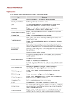 3
3 -
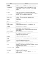 4
4 -
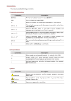 5
5 -
 6
6 -
 7
7 -
8
-
9
-
10
-
11
-
12
-
13
-
14
-
15
-
16
-
17
-
18
-
19
-
20
-
21
-
22
-
23
-
24
-
25
-
26
-
27
-
28
-
29
-
30
-
31
-
32
-
33
-
34
-
35
-
36
-
37
-
38
-
39
-
40
-
41
-
42
-
43
-
44
-
45
-
46
-
47
-
48
-
49
-
50
-
51
-
52
-
53
-
54
-
55
-
56
-
57
-
58
-
59
-
60
-
61
-
62
-
63
-
64
-
65
-
66
-
67
-
68
-
69
-
70
-
71
-
72
-
73
-
74
-
75
-
76
-
77
-
78
-
79
-
80
-
81
-
82
-
83
-
84
-
85
-
86
-
87
-
88
-
89
-
90
-
91
-
92
-
93
-
94
-
95
-
96
-
97
-
98
-
99
-
100
-
101
-
102
-
103
-
104
-
105
-
106
-
107
-
108
-
109
-
110
-
111
-
112
-
113
-
114
-
115
-
116
-
117
-
118
-
119
-
120
-
121
-
122
-
123
-
124
-
125
-
126
-
127
-
128
-
129
-
130
-
131
-
132
-
133
-
134
-
135
-
136
-
137
-
138
-
139
-
140
-
141
-
142
-
143
-
144
-
145
-
146
-
147
-
148
-
149
-
150
-
151
-
152
-
153
-
154
-
155
-
156
-
157
-
158
-
159
-
160
-
161
-
162
-
163
-
164
-
165
-
166
-
167
-
168
-
169
-
170
-
171
-
172
-
173
-
174
-
175
-
176
-
177
-
178
-
179
-
180
-
181
-
182
-
183
-
184
-
185
-
186
-
187
-
188
-
189
-
190
-
191
-
192
-
193
-
194
-
195
-
196
-
197
-
198
-
199
-
200
-
201
-
202
-
203
-
204
-
205
-
206
-
207
-
208
-
209
-
210
-
211
-
212
-
213
-
214
-
215
-
216
-
217
-
218
-
219
-
220
-
221
-
222
-
223
-
224
-
225
-
226
-
227
-
228
-
229
-
230
-
231
-
232
-
233
-
234
-
235
-
236
-
237
-
238
-
239
-
240
-
241
-
242
-
243
-
244
-
245
-
246
-
247
-
248
-
249
-
250
-
251
-
252
-
253
-
254
-
255
-
256
-
257
-
258
-
259
-
260
-
261
-
262
-
263
-
264
-
265
-
266
-
267
-
268
-
269
-
270
-
271
-
272
-
273
-
274
-
275
-
276
-
277
-
278
-
279
-
280
-
281
-
282
-
283
-
284
-
285
-
286
-
287
-
288
-
289
-
290
-
291
-
292
-
293
-
294
-
295
-
296
-
297
-
298
-
299
-
300
-
301
-
302
-
303
-
304
-
305
-
306
-
307
-
308
-
309
-
310
-
311
-
312
-
313
-
314
-
315
-
316
-
317
-
318
-
319
-
320
-
321
-
322
-
323
-
324
-
325
-
326
-
327
-
328
-
329
-
330
-
331
-
332
-
333
-
334
-
335
-
336
-
337
-
338
-
339
-
340
-
341
-
342
-
343
-
344
-
345
-
346
-
347
-
348
-
349
-
350
-
351
-
352
-
353
-
354
-
355
-
356
-
357
-
358
-
359
-
360
-
361
-
362
-
363
-
364
-
365
-
366
-
367
-
368
-
369
-
370
-
371
-
372
-
373
-
374
-
375
-
376
-
377
-
378
-
379
-
380
-
381
-
382
-
383
-
384
-
385
-
386
-
387
-
388
-
389
-
390
-
391
-
392
-
393
-
394
-
395
-
396
-
397
-
398
-
399
-
400
-
401
-
402
-
403
-
404
-
405
-
406
-
407
-
408
-
409
-
410
-
411
-
412
-
413
-
414
-
415
-
416
-
417
-
418
-
419
-
420
-
421
-
422
-
423
-
424
-
425
-
426
-
427
-
428
-
429
-
430
-
431
-
432
-
433
-
434
-
435
-
436
-
437
-
438
-
439
-
440
-
441
-
442
-
443
-
444
-
445
-
446
-
447
-
448
-
449
-
450
-
451
-
452
-
453
-
454
-
455
-
456
-
457
-
458
-
459
-
460
-
461
-
462
-
463
-
464
-
465
-
466
-
467
-
468
-
469
-
470
-
471
-
472
-
473
-
474
-
475
-
476
-
477
-
478
-
479
-
480
-
481
-
482
-
483
-
484
-
485
-
486
-
487
-
488
-
489
-
490
-
491
-
492
-
493
-
494
-
495
-
496
-
497
-
498
-
499
-
500
-
501
-
502
-
503
-
504
-
505
 |
 |

3Com Baseline Switch 2900 Family
User Guide
Baseline Switch 2920-SFP Plus
Baseline Switch 2928-SFP Plus
Baseline Switch 2952-SFP Plus
Baseline Switch 2928-PWR Plus
Baseline Switch 2928-HPWR Plus
Manual Version:
6W10
2
-2009
0
810
www.3com.com
3Com Corporation
350 Campus Drive, Marlborough,
MA, USA 01752 3064