3Com 2928 User Guide - Page 218
VLAN-to-MSTI mapping table, IST, MSTI, Regional root bridge, between VLANs and MSTIs.
 |
UPC - 662705557113
View all 3Com 2928 manuals
Add to My Manuals
Save this manual to your list of manuals |
Page 218 highlights
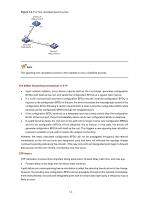
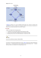
For example, all the devices in region A0 in Figure 1-4 have the same MST region configuration as follows: z The same region name, z The same VLAN-to-MSTI mapping configuration (VLAN 1 is mapped to MSTI 1, VLAN 2 to MSTI 2, and the rest to the common and internal spanning tree (CIST, that is, MSTI 0), and z The same MSTP revision level (not shown in the figure). Multiple MST regions can exist in a switched network. You can assign multiple devices to the same MST region. VLAN-to-MSTI mapping table As an attribute of an MST region, the VLAN-to-MSTI mapping table describes the mapping relationships between VLANs and MSTIs. In Figure 1-4, for example, the VLAN-to-MSTI mapping table of region A0 is: VLAN 1 is mapped to MSTI 1, VLAN 2 to MSTI 2, and the rest to CIST. MSTP achieves load balancing by means of the VLAN-to-MSTI mapping table. IST An internal spanning tree (IST) is a spanning tree that runs in an MST region. ISTs in all MST regions and the common spanning tree (CST) jointly constitute the common and internal spanning tree (CIST) of the entire network. An IST is a section of the CIST. An IST is a special MSTI. In Figure 1-4, for example, the CIST has a section in each MST region, and this section is the IST in the respective MST region. CST The CST is a single spanning tree that connects all MST regions in a switched network. If you regard each MST region as a "device", the CST is a spanning tree calculated by these devices through STP or RSTP. CSTs are indicated by red lines in Figure 1-4. CIST Jointly constituted by ISTs and the CST, the CIST is a single spanning tree that connects all devices in a switched network. In Figure 1-4, for example, the ISTs in all MST regions plus the inter-region CST constitute the CIST of the entire network. MSTI Multiple spanning trees can be generated in an MST region through MSTP, one spanning tree being independent of another. Each spanning tree is referred to as a multiple spanning tree instance (MSTI). In Figure 1-4, for example, multiple MSTIs can exist in each MST region, each MSTI corresponding to the specified VLANs. Regional root bridge The root bridge of the IST or an MSTI within an MST region is the regional root bridge of the IST or the MSTI. Based on the topology, different spanning trees in an MST region may have different regional roots. For example, in region D0 in Figure 1-4, the regional root of MSTI 1 is device B, while that of MSTI 2 is device C. 1-11
-
 1
1 -
2
-
3
-
4
-
5
-
6
-
7
-
8
-
9
-
10
-
11
-
12
-
13
-
14
-
15
-
16
-
17
-
18
-
19
-
20
-
21
-
22
-
23
-
24
-
25
-
26
-
27
-
28
-
29
-
30
-
31
-
32
-
33
-
34
-
35
-
36
-
37
-
38
-
39
-
40
-
41
-
42
-
43
-
44
-
45
-
46
-
47
-
48
-
49
-
50
-
51
-
52
-
53
-
54
-
55
-
56
-
57
-
58
-
59
-
60
-
61
-
62
-
63
-
64
-
65
-
66
-
67
-
68
-
69
-
70
-
71
-
72
-
73
-
74
-
75
-
76
-
77
-
78
-
79
-
80
-
81
-
82
-
83
-
84
-
85
-
86
-
87
-
88
-
89
-
90
-
91
-
92
-
93
-
94
-
95
-
96
-
97
-
98
-
99
-
100
-
101
-
102
-
103
-
104
-
105
-
106
-
107
-
108
-
109
-
110
-
111
-
112
-
113
-
114
-
115
-
116
-
117
-
118
-
119
-
120
-
121
-
122
-
123
-
124
-
125
-
126
-
127
-
128
-
129
-
130
-
131
-
132
-
133
-
134
-
135
-
136
-
137
-
138
-
139
-
140
-
141
-
142
-
143
-
144
-
145
-
146
-
147
-
148
-
149
-
150
-
151
-
152
-
153
-
154
-
155
-
156
-
157
-
158
-
159
-
160
-
161
-
162
-
163
-
164
-
165
-
166
-
167
-
168
-
169
-
170
-
171
-
172
-
173
-
174
-
175
-
176
-
177
-
178
-
179
-
180
-
181
-
182
-
183
-
184
-
185
-
186
-
187
-
188
-
189
-
190
-
191
-
192
-
193
-
194
-
195
-
196
-
197
-
198
-
199
-
200
-
201
-
202
-
203
-
204
-
205
-
206
-
207
-
208
-
209
-
210
-
211
-
212
-
 213
213 -
 214
214 -
 215
215 -
 216
216 -
 217
217 -
 218
218 -
 219
219 -
 220
220 -
 221
221 -
 222
222 -
 223
223 -
224
-
225
-
226
-
227
-
228
-
229
-
230
-
231
-
232
-
233
-
234
-
235
-
236
-
237
-
238
-
239
-
240
-
241
-
242
-
243
-
244
-
245
-
246
-
247
-
248
-
249
-
250
-
251
-
252
-
253
-
254
-
255
-
256
-
257
-
258
-
259
-
260
-
261
-
262
-
263
-
264
-
265
-
266
-
267
-
268
-
269
-
270
-
271
-
272
-
273
-
274
-
275
-
276
-
277
-
278
-
279
-
280
-
281
-
282
-
283
-
284
-
285
-
286
-
287
-
288
-
289
-
290
-
291
-
292
-
293
-
294
-
295
-
296
-
297
-
298
-
299
-
300
-
301
-
302
-
303
-
304
-
305
-
306
-
307
-
308
-
309
-
310
-
311
-
312
-
313
-
314
-
315
-
316
-
317
-
318
-
319
-
320
-
321
-
322
-
323
-
324
-
325
-
326
-
327
-
328
-
329
-
330
-
331
-
332
-
333
-
334
-
335
-
336
-
337
-
338
-
339
-
340
-
341
-
342
-
343
-
344
-
345
-
346
-
347
-
348
-
349
-
350
-
351
-
352
-
353
-
354
-
355
-
356
-
357
-
358
-
359
-
360
-
361
-
362
-
363
-
364
-
365
-
366
-
367
-
368
-
369
-
370
-
371
-
372
-
373
-
374
-
375
-
376
-
377
-
378
-
379
-
380
-
381
-
382
-
383
-
384
-
385
-
386
-
387
-
388
-
389
-
390
-
391
-
392
-
393
-
394
-
395
-
396
-
397
-
398
-
399
-
400
-
401
-
402
-
403
-
404
-
405
-
406
-
407
-
408
-
409
-
410
-
411
-
412
-
413
-
414
-
415
-
416
-
417
-
418
-
419
-
420
-
421
-
422
-
423
-
424
-
425
-
426
-
427
-
428
-
429
-
430
-
431
-
432
-
433
-
434
-
435
-
436
-
437
-
438
-
439
-
440
-
441
-
442
-
443
-
444
-
445
-
446
-
447
-
448
-
449
-
450
-
451
-
452
-
453
-
454
-
455
-
456
-
457
-
458
-
459
-
460
-
461
-
462
-
463
-
464
-
465
-
466
-
467
-
468
-
469
-
470
-
471
-
472
-
473
-
474
-
475
-
476
-
477
-
478
-
479
-
480
-
481
-
482
-
483
-
484
-
485
-
486
-
487
-
488
-
489
-
490
-
491
-
492
-
493
-
494
-
495
-
496
-
497
-
498
-
499
-
500
-
501
-
502
-
503
-
504
-
505
 |
 |