Acer Aspire 6530G Aspire 6530/6530G Quick Guide - Page 101
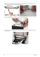
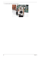
through the sockets., Connect the Camera Module cable as shown.
 |
View all Acer Aspire 6530G manuals
Add to My Manuals
Save this manual to your list of manuals |
Page 101 highlights
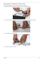
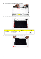
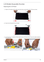
7. Pivot the LCD Panel down in place. NOTE: Ensure the CMOS and Inverter cables are not under the LCD Panel and correctly aligned. 8. Replace the six screws to secure the panel within the LCD module. 9. Locate the alignment pins (2) and replace the Camera Board taking care the pins protrude through the sockets. 10. Connect the Camera Module cable as shown. Chapter 3 91
-
 1
1 -
2
-
3
-
4
-
5
-
6
-
7
-
8
-
9
-
10
-
11
-
12
-
13
-
14
-
15
-
16
-
17
-
18
-
19
-
20
-
21
-
22
-
23
-
24
-
25
-
26
-
27
-
28
-
29
-
30
-
31
-
32
-
33
-
34
-
35
-
36
-
37
-
38
-
39
-
40
-
41
-
42
-
43
-
44
-
45
-
46
-
47
-
48
-
49
-
50
-
51
-
52
-
53
-
54
-
55
-
56
-
57
-
58
-
59
-
60
-
61
-
62
-
63
-
64
-
65
-
66
-
67
-
68
-
69
-
70
-
71
-
72
-
73
-
74
-
75
-
76
-
77
-
78
-
79
-
80
-
81
-
82
-
83
-
84
-
85
-
86
-
87
-
88
-
89
-
90
-
91
-
92
-
93
-
94
-
95
-
 96
96 -
 97
97 -
 98
98 -
 99
99 -
 100
100 -
 101
101 -
 102
102 -
 103
103 -
 104
104 -
 105
105 -
 106
106 -
107
-
108
-
109
-
110
-
111
-
112
-
113
-
114
-
115
-
116
-
117
-
118
-
119
-
120
-
121
-
122
-
123
-
124
-
125
-
126
-
127
-
128
-
129
-
130
-
131
-
132
-
133
-
134
-
135
-
136
-
137
-
138
-
139
-
140
-
141
-
142
-
143
-
144
-
145
-
146
-
147
-
148
-
149
-
150
-
151
-
152
-
153
-
154
-
155
-
156
-
157
-
158
-
159
-
160
-
161
-
162
-
163
-
164
-
165
-
166
-
167
-
168
-
169
-
170
-
171
-
172
-
173
-
174
-
175
-
176
-
177
-
178
-
179
-
180
-
181
-
182
-
183
-
184
-
185
-
186
-
187
-
188
-
189
-
190
-
191
-
192
-
193
-
194
-
195
-
196
-
197
-
198
-
199
-
200
-
201
-
202
-
203
-
204
-
205
-
206
-
207
-
208
-
209
-
210
-
211
-
212
-
213
-
214
-
215
-
216
-
217
-
218
-
219
-
220
-
221
-
222
-
223
-
224
 |
 |

Chapter 3
91
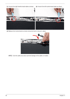
7.
Pivot the LCD Panel down in place.
NOTE:
Ensure the CMOS and Inverter cables are not under the LCD Panel and correctly aligned.
8.
Replace the six screws to secure the panel within the LCD module.
9.
Locate the alignment pins (2) and replace the
Camera Board taking care the pins protrude
through the sockets.
10.
Connect the Camera Module cable as shown.