Acer Aspire 6530G Aspire 6530/6530G Quick Guide - Page 105
Main Module Reassembly Procedure, Replacing the CPU, Replacing the Thermal Module - driver s
 |
View all Acer Aspire 6530G manuals
Add to My Manuals
Save this manual to your list of manuals |
Page 105 highlights
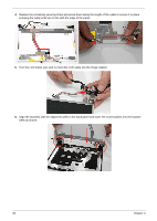
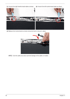
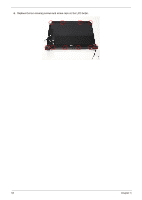
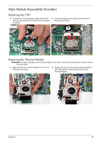
Main Module Reassembly Procedure Replacing the CPU 1. Carefully turn the mainboard upside down (CPU 2. Using a flat-tipped screw driver, lock the CPU in side up), and insert the CPU into the CPU bracket the socket as shown. as shown. Replacing the Thermal Module WARNING:To prevent damage to the Thermal Module or the CPU, hold the Thermal Module by both ends at the same time. 1. Align and place the Thermal Module in the on the mainboard as shown. 2. Replace the two securing screws (red) and tighten the three captive screws (blue) found on the Thermal Module. Chapter 3 95
-
 1
1 -
2
-
3
-
4
-
5
-
6
-
7
-
8
-
9
-
10
-
11
-
12
-
13
-
14
-
15
-
16
-
17
-
18
-
19
-
20
-
21
-
22
-
23
-
24
-
25
-
26
-
27
-
28
-
29
-
30
-
31
-
32
-
33
-
34
-
35
-
36
-
37
-
38
-
39
-
40
-
41
-
42
-
43
-
44
-
45
-
46
-
47
-
48
-
49
-
50
-
51
-
52
-
53
-
54
-
55
-
56
-
57
-
58
-
59
-
60
-
61
-
62
-
63
-
64
-
65
-
66
-
67
-
68
-
69
-
70
-
71
-
72
-
73
-
74
-
75
-
76
-
77
-
78
-
79
-
80
-
81
-
82
-
83
-
84
-
85
-
86
-
87
-
88
-
89
-
90
-
91
-
92
-
93
-
94
-
95
-
96
-
97
-
98
-
99
-
 100
100 -
 101
101 -
 102
102 -
 103
103 -
 104
104 -
 105
105 -
 106
106 -
 107
107 -
 108
108 -
 109
109 -
 110
110 -
111
-
112
-
113
-
114
-
115
-
116
-
117
-
118
-
119
-
120
-
121
-
122
-
123
-
124
-
125
-
126
-
127
-
128
-
129
-
130
-
131
-
132
-
133
-
134
-
135
-
136
-
137
-
138
-
139
-
140
-
141
-
142
-
143
-
144
-
145
-
146
-
147
-
148
-
149
-
150
-
151
-
152
-
153
-
154
-
155
-
156
-
157
-
158
-
159
-
160
-
161
-
162
-
163
-
164
-
165
-
166
-
167
-
168
-
169
-
170
-
171
-
172
-
173
-
174
-
175
-
176
-
177
-
178
-
179
-
180
-
181
-
182
-
183
-
184
-
185
-
186
-
187
-
188
-
189
-
190
-
191
-
192
-
193
-
194
-
195
-
196
-
197
-
198
-
199
-
200
-
201
-
202
-
203
-
204
-
205
-
206
-
207
-
208
-
209
-
210
-
211
-
212
-
213
-
214
-
215
-
216
-
217
-
218
-
219
-
220
-
221
-
222
-
223
-
224
 |
 |

Chapter 3
95
Main Module Reassembly Procedure
Replacing the CPU
Replacing the Thermal Module
WARNING:
To prevent damage to the Thermal Module or the CPU, hold the Thermal Module by both ends at
the same time.
1.
Carefully turn the mainboard upside down (CPU
side up), and insert the CPU into the CPU bracket
as shown.
2.
Using a flat-tipped screw driver, lock the CPU in
the socket as shown.
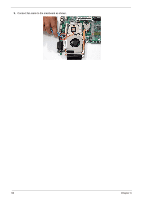
1.
Align and place the Thermal Module in the on the
mainboard as shown.
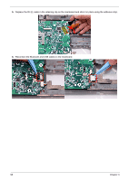
2.
Replace the two securing screws (red) and tighten
the three captive screws (blue) found on the
Thermal Module.