Acer Aspire 6530G Aspire 6530/6530G Quick Guide - Page 78
Removing the Upper Base, Remove the LCD module. See Removing the LCD Module
 |
View all Acer Aspire 6530G manuals
Add to My Manuals
Save this manual to your list of manuals |
Page 78 highlights
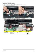
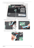
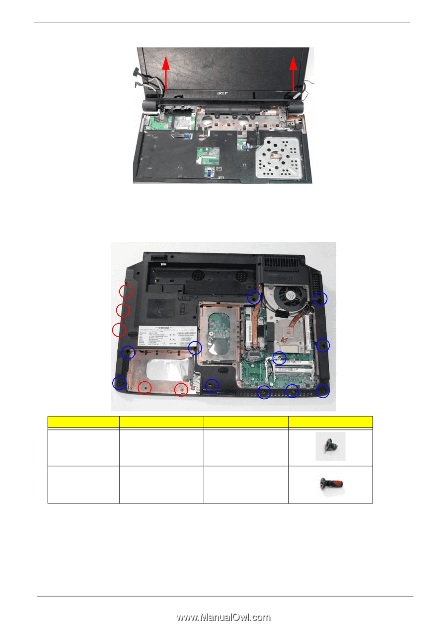
4. Carefully remove the LCD module from the chassis. Removing the Upper Base 1. Remove the LCD module. See "Removing the LCD Module" on page 67. 2. Turn the computer over. Remove the ten screws on the bottom panel. Step Upper Cover (Red call out) Upper Cover (Blue call out) Size M2.0*3.0-I-NI-NYLOK 2 Quantity M2.5*6.5-I 11 (BZN(NYLOK-RED) Screw Type 68 Chapter 3
-
 1
1 -
2
-
3
-
4
-
5
-
6
-
7
-
8
-
9
-
10
-
11
-
12
-
13
-
14
-
15
-
16
-
17
-
18
-
19
-
20
-
21
-
22
-
23
-
24
-
25
-
26
-
27
-
28
-
29
-
30
-
31
-
32
-
33
-
34
-
35
-
36
-
37
-
38
-
39
-
40
-
41
-
42
-
43
-
44
-
45
-
46
-
47
-
48
-
49
-
50
-
51
-
52
-
53
-
54
-
55
-
56
-
57
-
58
-
59
-
60
-
61
-
62
-
63
-
64
-
65
-
66
-
67
-
68
-
69
-
70
-
71
-
72
-
 73
73 -
 74
74 -
 75
75 -
 76
76 -
 77
77 -
 78
78 -
 79
79 -
 80
80 -
 81
81 -
 82
82 -
 83
83 -
84
-
85
-
86
-
87
-
88
-
89
-
90
-
91
-
92
-
93
-
94
-
95
-
96
-
97
-
98
-
99
-
100
-
101
-
102
-
103
-
104
-
105
-
106
-
107
-
108
-
109
-
110
-
111
-
112
-
113
-
114
-
115
-
116
-
117
-
118
-
119
-
120
-
121
-
122
-
123
-
124
-
125
-
126
-
127
-
128
-
129
-
130
-
131
-
132
-
133
-
134
-
135
-
136
-
137
-
138
-
139
-
140
-
141
-
142
-
143
-
144
-
145
-
146
-
147
-
148
-
149
-
150
-
151
-
152
-
153
-
154
-
155
-
156
-
157
-
158
-
159
-
160
-
161
-
162
-
163
-
164
-
165
-
166
-
167
-
168
-
169
-
170
-
171
-
172
-
173
-
174
-
175
-
176
-
177
-
178
-
179
-
180
-
181
-
182
-
183
-
184
-
185
-
186
-
187
-
188
-
189
-
190
-
191
-
192
-
193
-
194
-
195
-
196
-
197
-
198
-
199
-
200
-
201
-
202
-
203
-
204
-
205
-
206
-
207
-
208
-
209
-
210
-
211
-
212
-
213
-
214
-
215
-
216
-
217
-
218
-
219
-
220
-
221
-
222
-
223
-
224
 |
 |
68
Chapter 3
4.
Carefully remove the LCD module from the chassis.
Removing the Upper Base
1.
Remove the LCD module. See “Removing the LCD Module” on page 67.
2.
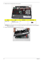
Turn the computer over. Remove the ten screws on the bottom panel.
Step
Size
Quantity
Screw Type
Upper Cover
(Red call out)
M2.0*3.0-I-NI-NYLOK
2
Upper Cover
(Blue call out)
M2.5*6.5-I
(BZN(NYLOK-RED)
11