Acer Aspire 6530G Aspire 6530/6530G Quick Guide - Page 70
Removing the Switch Cover, CAUTION, IMPORTANT, Quantity, Screw Type
 |
View all Acer Aspire 6530G manuals
Add to My Manuals
Save this manual to your list of manuals |
Page 70 highlights
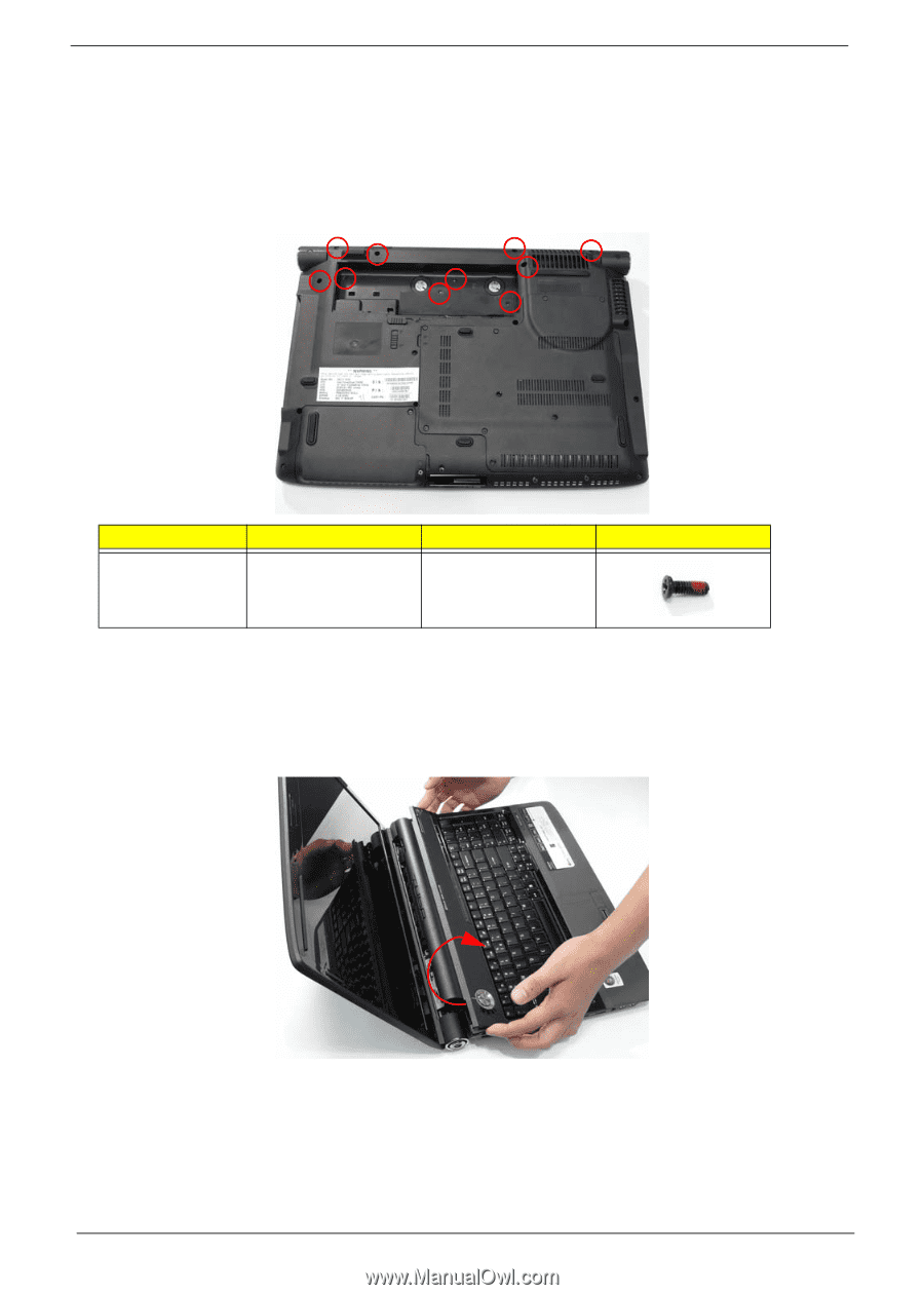
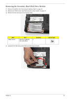
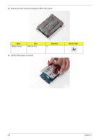
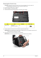
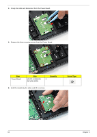
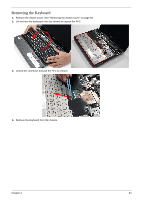
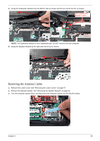
Removing the Switch Cover CAUTION: Using tools to remove the Switch Cover may cause damage to the outer casing. It is recommended that only fingers are used to remove the Switch Cover. 1. See "Removing the Battery Pack" on page 44. 2. Place the computer on a clean dry surface. 3. Locate and remove the ten securing screws on the bottom of the computer. Step Switch Cover Size M2.5*6.5-I (BZN(NYLOK-RED) Quantity 10 Screw Type 4. Turn the computer over and open the LCD module to expose the Switch Cover. IMPORTANT:The LCD module does not fully extend. Damage will occur if you attempt to extend the LCD module beyond the manufacturer's design. 5. Lift the Switch Cover as shown, and place over the keyboard. IMPORTANT:Do not remove at this point. FFC cables are still attached on the underside. 60 Chapter 3
-
 1
1 -
2
-
3
-
4
-
5
-
6
-
7
-
8
-
9
-
10
-
11
-
12
-
13
-
14
-
15
-
16
-
17
-
18
-
19
-
20
-
21
-
22
-
23
-
24
-
25
-
26
-
27
-
28
-
29
-
30
-
31
-
32
-
33
-
34
-
35
-
36
-
37
-
38
-
39
-
40
-
41
-
42
-
43
-
44
-
45
-
46
-
47
-
48
-
49
-
50
-
51
-
52
-
53
-
54
-
55
-
56
-
57
-
58
-
59
-
60
-
61
-
62
-
63
-
64
-
 65
65 -
 66
66 -
 67
67 -
 68
68 -
 69
69 -
 70
70 -
 71
71 -
 72
72 -
 73
73 -
 74
74 -
 75
75 -
76
-
77
-
78
-
79
-
80
-
81
-
82
-
83
-
84
-
85
-
86
-
87
-
88
-
89
-
90
-
91
-
92
-
93
-
94
-
95
-
96
-
97
-
98
-
99
-
100
-
101
-
102
-
103
-
104
-
105
-
106
-
107
-
108
-
109
-
110
-
111
-
112
-
113
-
114
-
115
-
116
-
117
-
118
-
119
-
120
-
121
-
122
-
123
-
124
-
125
-
126
-
127
-
128
-
129
-
130
-
131
-
132
-
133
-
134
-
135
-
136
-
137
-
138
-
139
-
140
-
141
-
142
-
143
-
144
-
145
-
146
-
147
-
148
-
149
-
150
-
151
-
152
-
153
-
154
-
155
-
156
-
157
-
158
-
159
-
160
-
161
-
162
-
163
-
164
-
165
-
166
-
167
-
168
-
169
-
170
-
171
-
172
-
173
-
174
-
175
-
176
-
177
-
178
-
179
-
180
-
181
-
182
-
183
-
184
-
185
-
186
-
187
-
188
-
189
-
190
-
191
-
192
-
193
-
194
-
195
-
196
-
197
-
198
-
199
-
200
-
201
-
202
-
203
-
204
-
205
-
206
-
207
-
208
-
209
-
210
-
211
-
212
-
213
-
214
-
215
-
216
-
217
-
218
-
219
-
220
-
221
-
222
-
223
-
224
 |
 |