Asus AP1720-E1 User Guide
Asus AP1720-E1 Manual
 |
View all Asus AP1720-E1 manuals
Add to My Manuals
Save this manual to your list of manuals |
Asus AP1720-E1 manual content summary:
- Asus AP1720-E1 | User Guide - Page 1
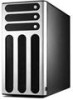
AP1720-E1 Dual Intel® Xeon 5U Rackmount Server 533MHz Front Side Bus User Guide - Asus AP1720-E1 | User Guide - Page 2
, and should not be construed as a commitment by ASUS. ASUS assumes no responsibility or liability for any errors or inaccuracies that may appear in this manual, including the products and software described in it. Product warranty or service will not be extended if: (1) the product is repaired - Asus AP1720-E1 | User Guide - Page 3
this guide vii 11 2.5 Front panel assembly 2-12 2.5.1 Removing the front panel assembly 2-12 2.5.2 Re-installing the front panel assembly 2-14 2.6 5.25-inch drives 2-15 2.7 Hard disk drives 2-18 2.7.1 Installing a hot-swap SCSI HDD 2-18 2.7.2 Installing an IDE HDD 2-20 2.8 Expansion cards - Asus AP1720-E1 | User Guide - Page 4
Removable components 2-36 2.10.1 Chassis fan 2-36 2.10.2 HDD fans 2-37 2.10.3 SCSI backplanes 2-39 2.10.4 Power supply module 2-41 2.10.5 Chapter 3: Installation options 3-1 3.1 Installing a second SCSI drive cage 3-2 3.2 Installing an IDE drive cage 3-5 3.3 Mounting the system to a rack - Asus AP1720-E1 | User Guide - Page 5
, if not installed and used in accordance with manufacturer's instructions, may cause harmful interference to radio communications. However, there use of shielded cables for connection of the monitor to the graphics card is required to assure compliance with FCC regulations. Changes or modifications - Asus AP1720-E1 | User Guide - Page 6
service technician or your dealer. Operation Safety • Any mechanical operation on this server must be conducted by certified or experienced engineers. • Before operating the server, carefully read all the manuals included with the server instructions. CD-ROM Drive Safety Warning CLASS 1 LASER - Asus AP1720-E1 | User Guide - Page 7
, and experienced users with at least basic knowledge of configuring a server. Contents This guide contains the following parts: 1. Chapter 1: Product Introduction This chapter describes the general features of the AP1720-E1 server. It includes sections on front panel and rear panel specifications - Asus AP1720-E1 | User Guide - Page 8
, and for product and software updates. 1. ASUS PC-DL Deluxe motherboard user guide This manual contains detailed information about the PC-DL Deluxe motherboard. 2. ASUS websites The ASUS websites worldwide provide updated information for all ASUS hardware and software products. Refer to the - Asus AP1720-E1 | User Guide - Page 9
Product introduction Chapter 1 This chapter describes the general features of the barebone server. It includes sections on front panel and rear panel specifications. ASUS AP1720-E1 user guide 1-1 - Asus AP1720-E1 | User Guide - Page 10
Bundled CDs • AP1720-E1 support CD • ASWM software CD • TrendMicro® ServerProtect® CD 6) Documentation • ASUS AP1720-E1 user guide • ASUS PC-DL Deluxe user guide 7) Optional items • ASUS AK25 rackmount rail kit • AK25 internal HDD cage (non-hot swap) HDD Bays AS8 (8 SCSI ) AS4 (4 SCSI) AI4 (4 IDE - Asus AP1720-E1 | User Guide - Page 11
specifications The ASUS AP1720-E1 is a barebone server system featuring the ASUS PC-DL Deluxe motherboard. The server supports dual Hardware monitors Power supply Pedestal or rackmount 5U with removable front door bezel and chassis foot stand or roller-wheels. ASUS PC-DL Deluxe (ATX form factor: - Asus AP1720-E1 | User Guide - Page 12
1.3 Front panel features The AP1720-E1 chassis displays a stylish front bezel with lock. The bezel covers bays are available. CD-ROM drive 2 empty 5.25-inch bays Power button Reset button Message LED HDD access LED Power LED Floppy disk drive IEEE 1394 port 4 USB 2.0 ports Microphone jack Line Out - Asus AP1720-E1 | User Guide - Page 13
supply module. Power supply module P/S2 mouse port P/S2 keyboard port Parallel port Serial ports IEEE 1394 port 4 USB 2.0 ports Gigabit LAN port Audio ports SCSI port (optional) Power connector 12cm fan vent Chassis lock Expansion slots ASUS AP1720-E1 barebone server 1-5 - Asus AP1720-E1 | User Guide - Page 14
Internal features The barebone server system includes the basic components as shown. AS8 (8-SCSI configuration) 1 8 10 2 3 6 4 9 7 5 1. Power supply cage 2. CD-ROM drive 3. 2 x 5.25-inch drive bays 4. first drive cage (upper) 5. second drive cage (lower) 6. HDD fan 1 7. HDD fan 2 (optional - Asus AP1720-E1 | User Guide - Page 15
AS4 (4-SCSI configuration) AI4 (4-IDE configuration) ASUS AP1720-E1 barebone server 1-7 - Asus AP1720-E1 | User Guide - Page 16
Green Red Red-Blinking Blinking Bridge board connected to backplane Installed HDD is in good condition HDD failure HDD rebuilding using the RAID card SAF-TE* function Read/write data into the HDD *SCSI Access Fault-Tolerant Enclosure The Power, HDD Access, and Message LEDs are visible even if the - Asus AP1720-E1 | User Guide - Page 17
Chapter 2 This chapter lists the hardware setup procedures that you have to perform when installing or removing system components. Hardware setup ASUS AP1720-E1 barebone server 2-1 - Asus AP1720-E1 | User Guide - Page 18
2.1 Chassis cover The chassis features a "screwless design" that allows convenient assembly and disassembly. Simply push or slide mechanical bolts 2.1.1 Removing the side cover 1. Push up the chassis lock (blue bolt) on the rear panel to release the side cover. 1 2. Slide the side cover for about - Asus AP1720-E1 | User Guide - Page 19
cards; replace fans and power supply; and connect the system cables. You may need to remove some of the installed components to access the DIMM sockets and internal connectors. Refer to section "2.10 Removable components" for instructions the side cover. 1 2 3 ASUS AP1720-E1 barebone server 2-3 - Asus AP1720-E1 | User Guide - Page 20
2.2 Motherboard information The barebone server comes with the ASUS PC-DL Deluxe motherboard already installed. The motherboard is secured to the chassis by nine (9) screws as indicated by circles in the illustration below. Refer to the motherboard user guide for detailed information on the - Asus AP1720-E1 | User Guide - Page 21
chassis fan attached to the inner side of the rear panel to allow enough space for the installation. Refer to section "2.10 Removable components" for instructions. ASUS AP1720-E1 barebone server 2-5 - Asus AP1720-E1 | User Guide - Page 22
2.3.1 Installing a CPU Follow these steps to install a CPU. 1. Locate the 604-pin CPU1 socket on the motherboard. Flip up the socket lever and push it all the way to the other side. Make sure that the socket lever is pushed back all the way, otherwise the CPU does not fit in completely. 2. Position - Asus AP1720-E1 | User Guide - Page 23
the thermal plates, refer to the picture below for the correct matching of the motherboard and thermal plate holes. Motherboard hole Standoff CPU thermal plate ASUS AP1720-E1 barebone server 2-7 - Asus AP1720-E1 | User Guide - Page 24
Make sure that you have applied the thermal grease to the top of the CPU before installing the heatsink and fan! To install the CPU heatsink and fan: 1. Place the heatsink with fan assembly on top of the installed CPU1. Make sure it fits the screw holes of the heatsink bracket at the bottom of the - Asus AP1720-E1 | User Guide - Page 25
heatsink and fan assembly for the second CPU, then connect the fan cable to the fan connector labeled CPUFAN2. CPUFAN1 cable plug CPUFAN2 cable plug ASUS AP1720-E1 barebone server 2-9 - Asus AP1720-E1 | User Guide - Page 26
2.4 System memory The motherboard comes with four Double Data Rate (DDR) Dual Inline Memory Module (DIMM) sockets. These sockets support up to 4GB system memory using 184-pin unbuffered ECC or non-ECC PC2700/ PC2100 DDR DIMMs, and allow up to 5.33GB/s data transfer rate. - Asus AP1720-E1 | User Guide - Page 27
the upper HDD fan cage. Refer to section "2.10 Removable components" for instructions. 1. Unlock supporting the DIMM with your fingers, press the retaining clips outward simultaneously to release the DIMM from the socket. 2. Remove the DIMM from the socket. ASUS AP1720-E1 barebone server 2-11 - Asus AP1720-E1 | User Guide - Page 28
2.5 Front panel assembly 2.5.1 Removing the front panel assembly Before you can install a 5.25-inch drive, you should first remove the front panel assembly (front bezel and front panel cover). The front panel assembly is attached to the chassis through four hooked tabs on the left side and four - Asus AP1720-E1 | User Guide - Page 29
3. Unhook the hinge-like tabs from the holes on the right side of the front panel to completely detach the front panel assembly from the chassis. Do not use too much force when removing the front panel assembly. Hinge-like tab ASUS AP1720-E1 barebone server 2-13 - Asus AP1720-E1 | User Guide - Page 30
2.5.2 Re-installing the front panel assembly To re-install the front panel assembly (front bezel and front panel cover): 1. Insert the four hinge-like tabs to the holes on the right edge of the chassis. 2. Swing the front panel to the left and fit the four (4) hooked tabs to the left side of the - Asus AP1720-E1 | User Guide - Page 31
drive bay, slide the drive bay lock by pushing it to the left to release the drive lock bar. Drive lock bar Drive bay lock ASUS AP1720-E1 barebone server 2-15 - Asus AP1720-E1 | User Guide - Page 32
the bar lock, carefully insert a 5.25-inch drive into the bay, until the back of the drive aligns to the rear edge of the drive cage. Due to space constraints inside the chassis, do not insert the drive all the way at this time. This will allow you enough space to - Asus AP1720-E1 | User Guide - Page 33
the bay cover. Bay cover tabs 10. Re-install the front panel assembly when done. Refer to section "2.5.2 Re-installing the front panel assembly" for instructions. ASUS AP1720-E1 barebone server 2-17 - Asus AP1720-E1 | User Guide - Page 34
2.7 Hard disk drives 2.7.1 Installing a hot-swap SCSI HDD To install a SCSI hard disk drive: 1. Open the front bezel the drive tray out of the bay. 4. An empty drive tray requires a metal bracket for support. Use a Phillips (cross) screwdriver to remove the bracket if you wish to install a hard - Asus AP1720-E1 | User Guide - Page 35
5. Place an SCA SCSI hard disk into the drive tray, and secure it with four screws. 6. Carefully insert drive tray and push it all the way , and secures the drive tray in place. The drive tray is correctly placed when its front edge aligns with the bay edge. ASUS AP1720-E1 barebone server 2-19 - Asus AP1720-E1 | User Guide - Page 36
2.7.2 Installing an IDE HDD If your system is an IDE model, your package comes with first and second drive cages. Installing into a bay on the first drive cage To install a drive from the front panel opening: 1. Remove the front panel assembly. Refer to section 2.5.1 for instructions. 2. Use a - Asus AP1720-E1 | User Guide - Page 37
HDD for the setting description. The setting "Cable Select" is recommended. 5. Carefully insert the drive into a bay on the front panel. 6. Push the drive all the way to the depth of the bay until the rail locks clicks, indicating that the drive is securely in place. ASUS AP1720-E1 barebone server - Asus AP1720-E1 | User Guide - Page 38
drives. 9. Re-install the front panel assembly when done. Installing into a bay on the second drive cage To install an internal drive : 1. Remove the side cover. Refer to section 2.1.1 for instructions. 2. Use a Phillips (cross) screwdriver to attach Rail 2 to the side of the drive with two screws - Asus AP1720-E1 | User Guide - Page 39
to the label pasted on the HDD for the setting description. The setting "Cable Select" is recommended. 5. Carefully insert the drive into a bay on the second drive cage as shown. 6. Connect the IDE when done. Refer to section "21.2 Installing the side cover." ASUS AP1720-E1 barebone server 2-23 - Asus AP1720-E1 | User Guide - Page 40
dummy cover Except on the 8-SCSI configuration model (AS8), the HDD dummy covers come pre-installed on the front panel bezel. In case you removed the covers, follow these steps to re-install them. To install an HDD dummy cover: 1. From the inside of the front panel assembly, insert the flat end of - Asus AP1720-E1 | User Guide - Page 41
where you wish to install the expansion card. Release the card lock by pressing the center tabs and pushing outward. Set the card lock aside for later use. Card lock tabs 2. Carefully install an expansion card making sure that it is properly seated on the slot. ASUS AP1720-E1 barebone server 2-25 - Asus AP1720-E1 | User Guide - Page 42
3. When the card is in place, secure it with the plastic card lock that you removed earlier. Card lock tab 2-26 Chapter 2: Hardware setup - Asus AP1720-E1 | User Guide - Page 43
guides that keep the expansion cards firmly seated on the slots. 1. The internal drive cage is optional and separately purchased. See section "Chapter 3 Optional components" for instructions on installing the drive cage. 2. The AS4 (4-SCSI configuration) and AI4 (4-IDE configuration) models support - Asus AP1720-E1 | User Guide - Page 44
in place, secure it with the plastic card lock that you removed earlier. 2.8.3 Removing an expansion card To remove an expansion card: 1. Remove the plastic card lock that secures the expansion card. Card lock tabs 2. Firmly hold the expansion card and pull it out of the slot. 3. Place the plastic - Asus AP1720-E1 | User Guide - Page 45
HDD fan 1 6. Front panel USB (4 ports) 7. Front panel 1394 8. Chassis intrusion 9. Front panel LEDs 10. Secondary IDE (optical drive) 11. SMBus panel to backplane 12. Floppy disk Refer to the motherboard user guide for detailed information on the connectors. ASUS AP1720-E1 barebone server 2-29 - Asus AP1720-E1 | User Guide - Page 46
trays. First backplane Disk drive 1 SCSI ID = 0 HDD status LEDs Disk drive 2 SCSI ID = 1 Disk drive 3 SCSI ID = 2 HDD activity LEDs Disk drive 4 SCSI ID = 3 If your barebone server supports a hot swap configuration for eight (8) hard disks, a second SCSI backplane comes with the system to - Asus AP1720-E1 | User Guide - Page 47
the power connectors, SCSI interfaces for the SCSI/RAID card and terminator, and SMBus connectors. The following picture shows a two-backplane configuration in a cascade connection. First SCSI backplane Cascade connection SCSI terminator Second SCSI backplane ASUS AP1720-E1 barebone server 2-31 - Asus AP1720-E1 | User Guide - Page 48
from the power supply) Fan connector (for HDD fan) SMBus connector (upper 6-1 pins) (connects the SMB cable from the motherboard) 68-pin SCSI connector (connects the SCSI cable 68-pin SCSI connector from the SCSI/RAID card) (with SCSI multi-mode terminator) 2-32 Chapter 2: Hardware setup - Asus AP1720-E1 | User Guide - Page 49
SCSI cable to the second backplane) Second backplane SMBus connector (upper 6-1 pins) (connects the SMB cable from the first backplane) 68-pin SCSI connector (connects the SCSI cable from the first backplane) 68-pin SCSI connector (with SCSI multi-mode terminator) ASUS AP1720-E1 barebone server - Asus AP1720-E1 | User Guide - Page 50
shorted. Refer to the following tables for the jumper settings and the appropriate ID# for each SCSI HDD bay. Cascade configuration First backplane (BPB1) J1 setting (1-3 shorted, 2-4 shorted) Device SCSI ID# Drive Bay 1 ID0 Drive Bay 2 ID1 Drive Bay 3 ID2 Drive Bay 4 ID3 GEM SAF-TE - Asus AP1720-E1 | User Guide - Page 51
GEM SAF-TE ID15 (SCSI channel-0) Second backplane (BPB2) J1 setting (1-3 shorted, 2-4 shorted) Device SCSI ID# Drive Bay 5 ID0 Drive Bay 6 ID1 Drive Bay 7 ID2 Drive Bay 8 ID3 GEM SAF-TE ID15 (SCSI channel-1) SCSI ID7 is reserved for the SCSI card. ASUS AP1720-E1 barebone server 2-35 - Asus AP1720-E1 | User Guide - Page 52
devices, or when you need to replace defective components. This section tells how to remove the following components: 1. Chassis fan 2. HDD fans 3. SCSI backplanes 4. Power supply module 5. Floppy disk drive 6. Front I/O board 2.10.1 Chassis fan To remove the chassis fan: 1. Disconnect the 3-pin - Asus AP1720-E1 | User Guide - Page 53
the fan cage from the chassis. Due to space constraints inside the chassis, some cables may interfere with the removal of the fan cage. To easily remove the fan cage, try to slightly push it inward (toward the motherboard) before pulling it out of the chassis. ASUS AP1720-E1 barebone server 2-37 - Asus AP1720-E1 | User Guide - Page 54
caught up when you place the HDD fan. Outer side of fan cage Side tabs Inner edge of drive cage 3. Push the outer edge of the fan cage sideways to fit it to the drive cage. You hear a click when the fan cage correctly fits in place. 4. Secure the fan cage with the thumb screw. 2-38 Chapter - Asus AP1720-E1 | User Guide - Page 55
backplanes To remove a SCSI backplane: 1. Remove the HDD fan cage. Refer to section "2.10.2 HDD fans" for instructions. 2. Disconnect all cables from the backplane. When disconnecting a cable, hold edge, firmly hold the backplane and carefully slide it out. ASUS AP1720-E1 barebone server 2-39 - Asus AP1720-E1 | User Guide - Page 56
it fits. If correctly installed, the outer edge of the backplane aligns with the corner of the drive cage. 4. Connect the appropriate cables to the backplane. Refer to section "2.9.2 SCSI backplane connections" for information on backplane cabling. Rail-like dents 2-40 Chapter 2: Hardware setup - Asus AP1720-E1 | User Guide - Page 57
AUX (motherboard power connector) 3 4-pin plug (optical drive) 4 2 x 4-pin plugs (first backplane, if present) 5 2 x 4-pin plugs (second backplane, if present) 6 4-pin plug (floppy disk drive) ASUS AP1720-E1 barebone server 2-41 - Asus AP1720-E1 | User Guide - Page 58
from the chassis. Remove the metal plate completely. Metal plate bar 3. Use one hand to push the power supply module from inside the power supply cage, then carefully pull out the module from the chassis. Thumbscrew 2-42 Chapter 2: Hardware setup - Asus AP1720-E1 | User Guide - Page 59
rear panel. Be careful with the power supply cables when inserting the power supply module into the cage. Due to space constraints, the cables may get entangled with the installed components or other cables, . 5. Secure the metal plate with the thumb screw. ASUS AP1720-E1 barebone server 2-43 - Asus AP1720-E1 | User Guide - Page 60
You need to remove the front panel assembly before you can remove the floppy disk drive. Refer to section "2.5.1 Removing the front panel assembly" for instructions. To remove the floppy disk drive: 1. Remove the screw that secures the drive to the chassis. 2. Carefully pull out the drive from the - Asus AP1720-E1 | User Guide - Page 61
floppy drive vertically with the eject button on the left side (close to the HDDs). 2. Connect the drive signal cable and power cable. Eject button Red stripe to bay until the drive cage fits the front edge of the bay. 4. Secure the drive cage with a screw. ASUS AP1720-E1 barebone server 2-45 - Asus AP1720-E1 | User Guide - Page 62
need to remove the front panel assembly before you can remove the front I/O board. Refer to section "2.5.1 Removing the front panel assembly" for instructions. To remove the front I/O board: 1. Remove the screw that secures the front I/O board bracket to the front panel. 2. Carefully pull out the - Asus AP1720-E1 | User Guide - Page 63
until the bracket fits the front edge of the bay. 4. Secure the I/O board bracket with a screw. Audio connector (black) USB 2.0 connectors (blue) 1394 connector (red) ASUS AP1720-E1 barebone server 2-47 - Asus AP1720-E1 | User Guide - Page 64
10.7 Chassis footpads and roller wheels The barebone server system is shipped with four footpads attached to a rack (Refer to "Chapter 3 Installation options" of this user guide, and to the "Rackmount Kit" user guide for instructions) To remove the footpads: 1. Lay the system chassis on its side. - Asus AP1720-E1 | User Guide - Page 65
a Phillips screwdriver to remove the screws that secure the wheels to the bottom of the chassis. 3. Repeat step 2 to remove the other three roller wheels. ASUS AP1720-E1 barebone server 2-49 - Asus AP1720-E1 | User Guide - Page 66
2-50 Chapter 2: Hardware setup - Asus AP1720-E1 | User Guide - Page 67
Installation options Chapter 3 This chapter describes how to install optional components and devices into the barebone server and create your desired configuration. ASUS AP1720-E1 barebone server 3-1 - Asus AP1720-E1 | User Guide - Page 68
in the standard barebone system package. These items are purchased separately. 3.1 Installing a second SCSI drive cage Perform this installation if you wish to upgrade your 4-SCSI configuration system (AS4 model) to an 8-SCSI configuration. 4-SCSI configuration 8-SCSI configuration Clear the - Asus AP1720-E1 | User Guide - Page 69
screws. 5. Position the support bracket for the drive trays to the left side of the cage with the three protruding tabs matching the elongated holes on the chassis. Front screw holes Protruding tabs Screw holes SCSI drive tray support bracket ASUS AP1720-E1 barebone server Elongated holes for - Asus AP1720-E1 | User Guide - Page 70
chassis. 7. Secure the bracket with two screws in the holes indicated. Securing the bracket with the two screws also secures the left side of the SCSI drive cage. 3-4 Chapter 3: Installation options - Asus AP1720-E1 | User Guide - Page 71
in the way when you install the second drive cage. To install an IDE drive cage: 1. Position the drive cage into the bay with the screw hole tab on top and facing out. 2. Carefully slide the drive cage toward the front panel until it fits in place. Screw hole ASUS AP1720-E1 barebone server 3-5 - Asus AP1720-E1 | User Guide - Page 72
3. Make sure that the drive cage is fits snugly to the bay as shown. The drive cage is properly installed when it is parallel to the front panel, and the screw hole matches the hole of the first drive cage. 4. Secure the drive cage with a screw. Screw hole 3-6 Chapter 3: Installation options - Asus AP1720-E1 | User Guide - Page 73
Lock tab of top cover (bottom view) 3.3.3 Attach the rack rails Refer to the installation guide that came with the Rackmount Rail Kit for instructions on how to attach the rails and on the barebone server system and the corresponding rails on the industrial rack. ASUS AP1720-E1 barebone server 3-7 - Asus AP1720-E1 | User Guide - Page 74
3-8 Chapter 3: Installation options - Asus AP1720-E1 | User Guide - Page 75
Appendix This appendix gives information on the power supply that came with the barebone server. Power supply ASUS AP1720-E1 barebone server 3-1 - Asus AP1720-E1 | User Guide - Page 76
A.1 General description The server comes with an SSI-type 450W ATX power supply with universal AC input that includes PFC and ATX-compliant output cables and connectors. The power - Asus AP1720-E1 | User Guide - Page 77
regulation Output Voltage +3.33V +5V +12V -12V +5VSB Min (V) 3.16 4.8 11.52 -11.4 4.8 Nom (V) 3.30 5.00 12.00 -12.20 5.00 Max (V) 10 Over-voltage protection Voltage +3.33V +5V +12V +12V +5VSB Min (V) 3.9 5.7 13.3 -13.3 5.7 Max (V) 4.5 6.5 15.0 -15.0 6.5 ASUS AP1720-E1 barebone server A-3 - Asus AP1720-E1 | User Guide - Page 78
A-4 Chapter 3: Installation options
-
 1
1 -
 2
2 -
 3
3 -
 4
4 -
 5
5 -
 6
6 -
 7
7 -
8
-
9
-
10
-
11
-
12
-
13
-
14
-
15
-
16
-
17
-
18
-
19
-
20
-
21
-
22
-
23
-
24
-
25
-
26
-
27
-
28
-
29
-
30
-
31
-
32
-
33
-
34
-
35
-
36
-
37
-
38
-
39
-
40
-
41
-
42
-
43
-
44
-
45
-
46
-
47
-
48
-
49
-
50
-
51
-
52
-
53
-
54
-
55
-
56
-
57
-
58
-
59
-
60
-
61
-
62
-
63
-
64
-
65
-
66
-
67
-
68
-
69
-
70
-
71
-
72
-
73
-
74
-
75
-
76
-
77
-
78
 |
 |

Dual Intel
®
Xeon 5U Rackmount Server
533MHz Front Side Bus
AP1720-E1
User Guide