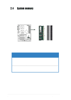
Asus AP1720-E1 User Guide - Page 28
Front panel assembly
 |
View all Asus AP1720-E1 manuals
Add to My Manuals
Save this manual to your list of manuals |
Page 28 highlights
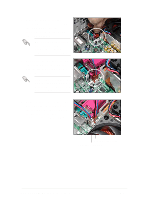
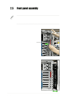
2.5 Front panel assembly 2.5.1 Removing the front panel assembly Before you can install a 5.25-inch drive, you should first remove the front panel assembly (front bezel and front panel cover). The front panel assembly is attached to the chassis through four hooked tabs on the left side and four hinge-like tabs on the right side. To remove the front panel assembly: 1. Press the lock lever (blue bar) on the front edge of the chassis to release the front panel assembly. Lock lever 2. Pull and swing the left edge of the front panel outward. 2-12 Chapter 2: Hardware setup
-
 1
1 -
2
-
3
-
4
-
5
-
6
-
7
-
8
-
9
-
10
-
11
-
12
-
13
-
14
-
15
-
16
-
17
-
18
-
19
-
20
-
21
-
22
-
 23
23 -
 24
24 -
 25
25 -
 26
26 -
 27
27 -
 28
28 -
 29
29 -
 30
30 -
 31
31 -
 32
32 -
 33
33 -
34
-
35
-
36
-
37
-
38
-
39
-
40
-
41
-
42
-
43
-
44
-
45
-
46
-
47
-
48
-
49
-
50
-
51
-
52
-
53
-
54
-
55
-
56
-
57
-
58
-
59
-
60
-
61
-
62
-
63
-
64
-
65
-
66
-
67
-
68
-
69
-
70
-
71
-
72
-
73
-
74
-
75
-
76
-
77
-
78
 |
 |
Chapter 2:
Hardware setup
2-12
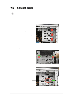
Before you can install a 5.25-inch drive, you should first remove the
front panel assembly (front bezel and front panel cover). The front
panel assembly is attached to the chassis through four
hooked tabs
on the left side and four
hinge-like tabs
on the right side.
To remove the front panel assembly:
1.
Press the lock lever (blue bar) on the
front edge of the chassis to release the
front panel assembly.
2.5
Front panel assembly
2.5.1
Removing the front panel assembly
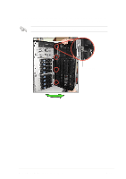
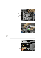
2.
Pull and swing the left edge of the front
panel outward.
Lock lever