Asus AP1720-E1 User Guide - Page 63
Insert the I/O board
 |
View all Asus AP1720-E1 manuals
Add to My Manuals
Save this manual to your list of manuals |
Page 63 highlights
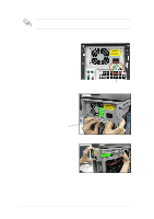
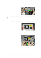
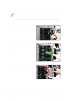
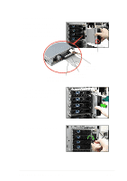
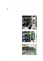
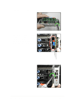
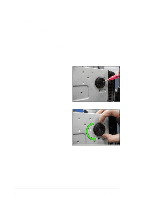
To install the front I/O board: 1. Place the I/O board in the bracket, component side up. Secure the front I/O board to the bracket with a screw. 2. Position the I/O board into the bay with the component side to the left (close to the HDDs). Connect the I/O cables to the connectors on the back of the I/O board. 3. Insert the I/O board into the bay until the bracket fits the front edge of the bay. 4. Secure the I/O board bracket with a screw. Audio connector (black) USB 2.0 connectors (blue) 1394 connector (red) ASUS AP1720-E1 barebone server 2-47
-
 1
1 -
2
-
3
-
4
-
5
-
6
-
7
-
8
-
9
-
10
-
11
-
12
-
13
-
14
-
15
-
16
-
17
-
18
-
19
-
20
-
21
-
22
-
23
-
24
-
25
-
26
-
27
-
28
-
29
-
30
-
31
-
32
-
33
-
34
-
35
-
36
-
37
-
38
-
39
-
40
-
41
-
42
-
43
-
44
-
45
-
46
-
47
-
48
-
49
-
50
-
51
-
52
-
53
-
54
-
55
-
56
-
57
-
 58
58 -
 59
59 -
 60
60 -
 61
61 -
 62
62 -
 63
63 -
 64
64 -
 65
65 -
 66
66 -
 67
67 -
 68
68 -
69
-
70
-
71
-
72
-
73
-
74
-
75
-
76
-
77
-
78
 |
 |
2-47
ASUS AP1720-E1 barebone server
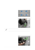
To install the front I/O board:
1.
Place the I/O board in the
bracket, component side up.
Secure the front I/O board to the
bracket with a screw.
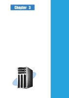
2.
Position the I/O board into the bay
with the component side to the
left (close to the HDDs). Connect
the I/O cables to the connectors
on the back of the I/O board.
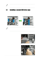
3.
Insert the I/O board
into the bay
until the
bracket fits the front
edge of the bay.
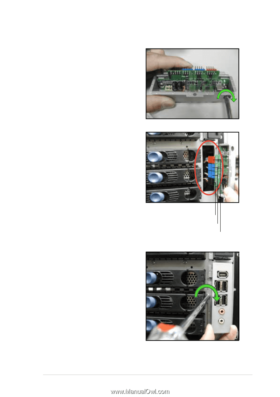
4.
Secure the I/O board bracket with
a screw.
1394 connector (red)
USB 2.0 connectors (blue)
Audio connector (black)