Asus AP1720-E1 User Guide - Page 19
Installing the side cover
 |
View all Asus AP1720-E1 manuals
Add to My Manuals
Save this manual to your list of manuals |
Page 19 highlights
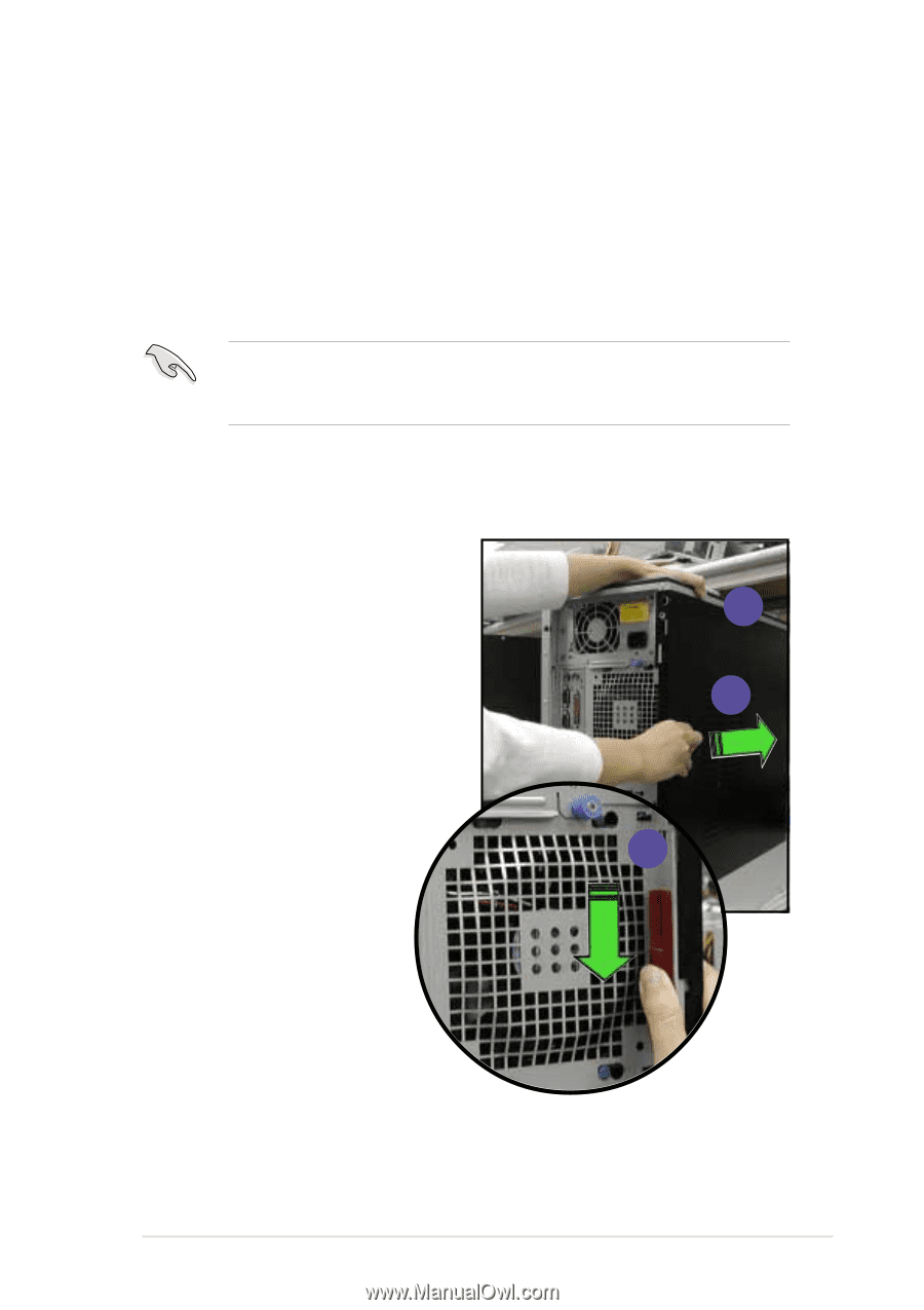
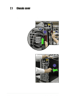
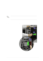
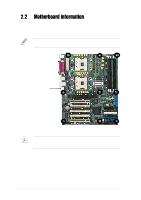
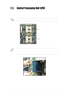
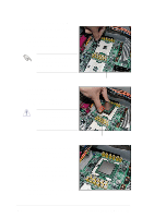
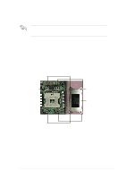
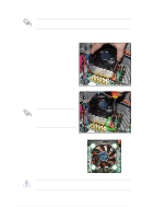
Viewing the internal structure Without the side cover, the internal structure and installed components of the barebone server vary depending on the model you purchased. Refer to section "1.5 Internal features" for the different model configurations. Perform the procedures in the succeeding sections to install the CPU, system memory, disk drives, and expansion cards; replace fans and power supply; and connect the system cables. You may need to remove some of the installed components to access the DIMM sockets and internal connectors. Refer to section "2.10 Removable components" for instructions. 2.1.2 Installing the side cover 1. Match and insert the hooks of the cover to the elongated holes on the side of the chassis. All the six hooks (three each on the top and bottom) of the cover must properly fit the designated holes. 2. Slide the cover toward the front until it snaps in place. 3. Push down the chassis lock to secure the side cover. 1 2 3 ASUS AP1720-E1 barebone server 2-3
-
 1
1 -
2
-
3
-
4
-
5
-
6
-
7
-
8
-
9
-
10
-
11
-
12
-
13
-
 14
14 -
 15
15 -
 16
16 -
 17
17 -
 18
18 -
 19
19 -
 20
20 -
 21
21 -
 22
22 -
 23
23 -
 24
24 -
25
-
26
-
27
-
28
-
29
-
30
-
31
-
32
-
33
-
34
-
35
-
36
-
37
-
38
-
39
-
40
-
41
-
42
-
43
-
44
-
45
-
46
-
47
-
48
-
49
-
50
-
51
-
52
-
53
-
54
-
55
-
56
-
57
-
58
-
59
-
60
-
61
-
62
-
63
-
64
-
65
-
66
-
67
-
68
-
69
-
70
-
71
-
72
-
73
-
74
-
75
-
76
-
77
-
78
 |
 |