Asus AP1720-E1 User Guide - Page 33
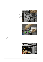
On the front panel assembly, detach the plastic bay cover opposite
 |
View all Asus AP1720-E1 manuals
Add to My Manuals
Save this manual to your list of manuals |
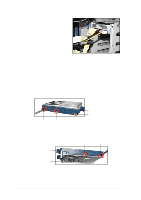
Page 33 highlights
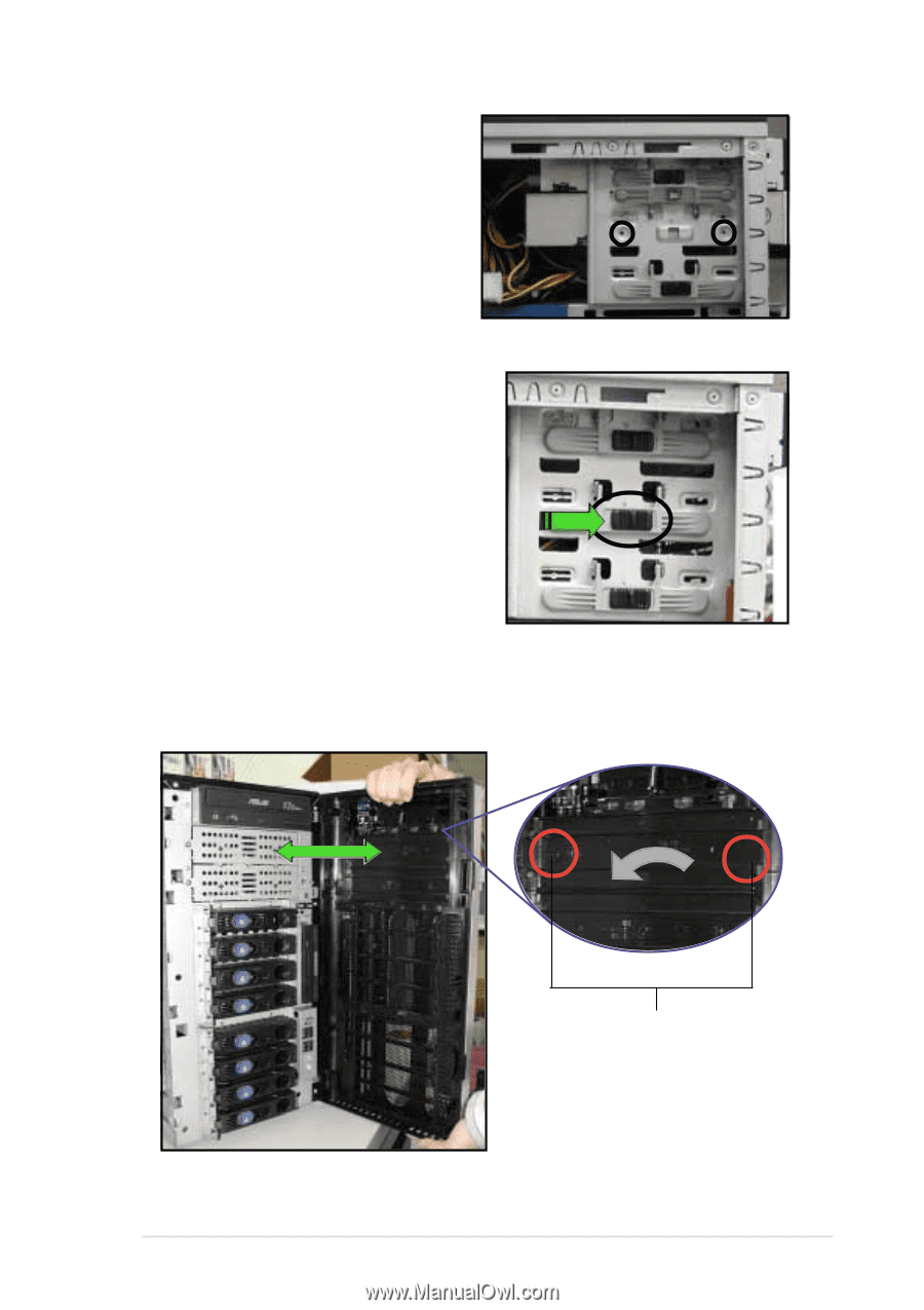
7. Make sure that the drive and bay holes align as shown. When in place, the drive protrudes about an inch from the front panel. 8. Pull down the bar lock and insert the lock pegs to the drive/bay holes, then push the drive lock to the right to secure the drive. 9. On the front panel assembly, detach the plastic bay cover opposite the 5.25-inch drive that you installed by pressing the two hooked tabs on each side of the bay cover. Bay cover tabs 10. Re-install the front panel assembly when done. Refer to section "2.5.2 Re-installing the front panel assembly" for instructions. ASUS AP1720-E1 barebone server 2-17
-
 1
1 -
2
-
3
-
4
-
5
-
6
-
7
-
8
-
9
-
10
-
11
-
12
-
13
-
14
-
15
-
16
-
17
-
18
-
19
-
20
-
21
-
22
-
23
-
24
-
25
-
26
-
27
-
 28
28 -
 29
29 -
 30
30 -
 31
31 -
 32
32 -
 33
33 -
 34
34 -
 35
35 -
 36
36 -
 37
37 -
 38
38 -
39
-
40
-
41
-
42
-
43
-
44
-
45
-
46
-
47
-
48
-
49
-
50
-
51
-
52
-
53
-
54
-
55
-
56
-
57
-
58
-
59
-
60
-
61
-
62
-
63
-
64
-
65
-
66
-
67
-
68
-
69
-
70
-
71
-
72
-
73
-
74
-
75
-
76
-
77
-
78
 |
 |
2-17
ASUS AP1720-E1 barebone server
7.
Make sure that the drive and bay
holes align as shown. When in
place, the drive protrudes about
an inch from the front panel.
8.
Pull down the bar lock and insert the
lock pegs to the drive/bay holes,
then push the drive lock to the right
to secure the drive.
9.
On the front panel assembly, detach the plastic bay cover opposite the
5.25-inch drive that you installed by pressing the two hooked tabs on
each side of the bay cover.
Bay cover tabs
10. Re-install the front panel assembly when done. Refer to section “2.5.2
Re-installing the front panel assembly” for instructions.