Asus AP1720-E1 User Guide - Page 12
Front panel features
 |
View all Asus AP1720-E1 manuals
Add to My Manuals
Save this manual to your list of manuals |
Page 12 highlights
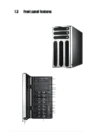
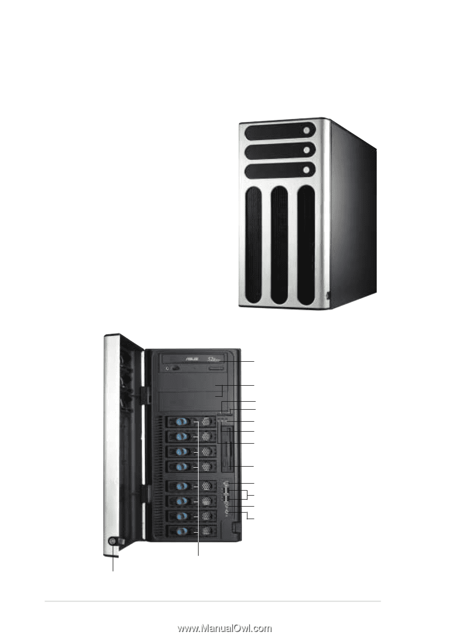
1.3 Front panel features The AP1720-E1 chassis displays a stylish front bezel with lock. The bezel covers the system components on the front panel and serves as security. Open the bezel to access the front panel components. The drive bays, power and reset buttons, LED indicators, CD-ROM drive, floppy drive, and four USB ports are located on the front panel. For future installation of 5.25-inch devices, two drive bays are available. CD-ROM drive 2 empty 5.25-inch bays Power button Reset button Message LED HDD access LED Power LED Floppy disk drive IEEE 1394 port 4 USB 2.0 ports Microphone jack Line Out jack Security lock Drive bays 1-4 Chapter 1: Product introduction
-
 1
1 -
2
-
3
-
4
-
5
-
6
-
 7
7 -
 8
8 -
 9
9 -
 10
10 -
 11
11 -
 12
12 -
 13
13 -
 14
14 -
 15
15 -
 16
16 -
 17
17 -
18
-
19
-
20
-
21
-
22
-
23
-
24
-
25
-
26
-
27
-
28
-
29
-
30
-
31
-
32
-
33
-
34
-
35
-
36
-
37
-
38
-
39
-
40
-
41
-
42
-
43
-
44
-
45
-
46
-
47
-
48
-
49
-
50
-
51
-
52
-
53
-
54
-
55
-
56
-
57
-
58
-
59
-
60
-
61
-
62
-
63
-
64
-
65
-
66
-
67
-
68
-
69
-
70
-
71
-
72
-
73
-
74
-
75
-
76
-
77
-
78
 |
 |
Chapter 1:
Product introduction
1-4
1.3
Front panel features
The AP1720-E1 chassis displays a stylish front bezel with lock. The bezel
covers the system components on the front panel and serves as security.
Open the bezel to access the front panel components.
The drive bays, power and reset
buttons, LED indicators, CD-ROM
drive, floppy drive, and four USB ports
are located on the front panel. For
future installation of 5.25-inch devices,
two drive bays are available.
CD-ROM drive
Floppy disk drive
2 empty 5.25-inch bays
Reset button
Power button
Message LED
HDD access LED
Power LED
4 USB 2.0 ports
Microphone jack
Line Out jack
IEEE 1394 port
Security lock
Drive bays