Asus AP1720-E1 User Guide - Page 57
Power supply module
 |
View all Asus AP1720-E1 manuals
Add to My Manuals
Save this manual to your list of manuals |
Page 57 highlights
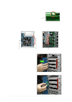
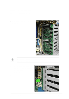
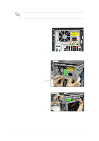
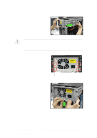
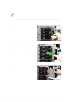
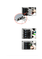
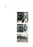
2.10.4 Power supply module You MUST disconnect all power cable plugs from the motherboard and other installed devices before removing the power supply. The picture below shows the motherboard and device connectors where the power plugs are connected. Refer also to Appendix at the end of this document for details on the power supply. 3 2 1 4 6 5 1 24-pin ATX (motherboard power connector) 2 8-pin +12V AUX (motherboard power connector) 3 4-pin plug (optical drive) 4 2 x 4-pin plugs (first backplane, if present) 5 2 x 4-pin plugs (second backplane, if present) 6 4-pin plug (floppy disk drive) ASUS AP1720-E1 barebone server 2-41
-
 1
1 -
2
-
3
-
4
-
5
-
6
-
7
-
8
-
9
-
10
-
11
-
12
-
13
-
14
-
15
-
16
-
17
-
18
-
19
-
20
-
21
-
22
-
23
-
24
-
25
-
26
-
27
-
28
-
29
-
30
-
31
-
32
-
33
-
34
-
35
-
36
-
37
-
38
-
39
-
40
-
41
-
42
-
43
-
44
-
45
-
46
-
47
-
48
-
49
-
50
-
51
-
 52
52 -
 53
53 -
 54
54 -
 55
55 -
 56
56 -
 57
57 -
 58
58 -
 59
59 -
 60
60 -
 61
61 -
 62
62 -
63
-
64
-
65
-
66
-
67
-
68
-
69
-
70
-
71
-
72
-
73
-
74
-
75
-
76
-
77
-
78
 |
 |

2-41
ASUS AP1720-E1 barebone server
2.10.4
Power supply module
You MUST disconnect all power cable plugs from the motherboard and
other installed devices before removing the power supply.
The picture below shows the motherboard and device connectors where
the power plugs are connected. Refer also to Appendix at the end of this
document for details on the power supply.
1
24-pin ATX (motherboard power connector)
2
8-pin +12V AUX (motherboard power connector)
3
4-pin plug (optical drive)
4
2 x 4-pin plugs (first backplane, if present)
5
2 x 4-pin plugs (second backplane, if present)
6
4-pin plug (floppy disk drive)
1
3
4
5
6
2