Asus AP1720-E1 User Guide - Page 48
One-backplane configuration
 |
View all Asus AP1720-E1 manuals
Add to My Manuals
Save this manual to your list of manuals |
Page 48 highlights
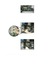
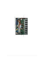
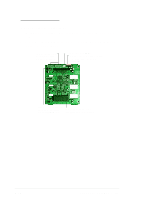
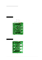
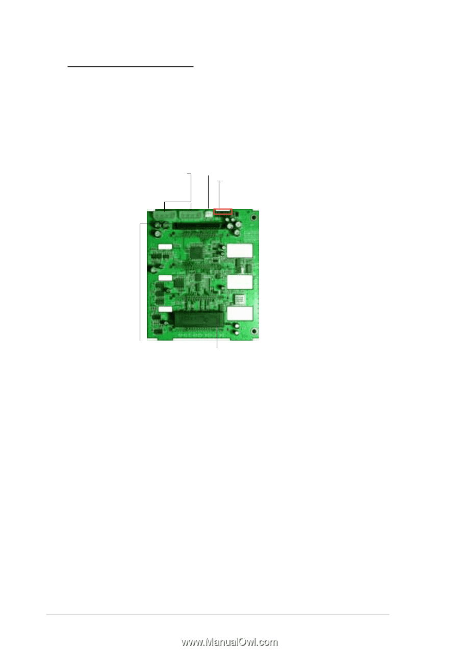
One-backplane configuration In a one-backplane configuration: • the upper SCSI interface of the backplane connects to the SCSI/RAID card • a SCSI multi-mode terminator (LVD/SE) is connected to the lower SCSI interface of the backplane Power connectors (connect power plugs from the power supply) Fan connector (for HDD fan) SMBus connector (upper 6-1 pins) (connects the SMB cable from the motherboard) 68-pin SCSI connector (connects the SCSI cable 68-pin SCSI connector from the SCSI/RAID card) (with SCSI multi-mode terminator) 2-32 Chapter 2: Hardware setup
-
 1
1 -
2
-
3
-
4
-
5
-
6
-
7
-
8
-
9
-
10
-
11
-
12
-
13
-
14
-
15
-
16
-
17
-
18
-
19
-
20
-
21
-
22
-
23
-
24
-
25
-
26
-
27
-
28
-
29
-
30
-
31
-
32
-
33
-
34
-
35
-
36
-
37
-
38
-
39
-
40
-
41
-
42
-
 43
43 -
 44
44 -
 45
45 -
 46
46 -
 47
47 -
 48
48 -
 49
49 -
 50
50 -
 51
51 -
 52
52 -
 53
53 -
54
-
55
-
56
-
57
-
58
-
59
-
60
-
61
-
62
-
63
-
64
-
65
-
66
-
67
-
68
-
69
-
70
-
71
-
72
-
73
-
74
-
75
-
76
-
77
-
78
 |
 |
Chapter 2:
Hardware setup
2-32
One-backplane configuration
In a
one-backplane
configuration:
•
the upper SCSI interface of the backplane connects to the SCSI/RAID
card
•
a SCSI multi-mode terminator (LVD/SE) is connected to the lower SCSI
interface of the backplane
Power connectors
(connect power plugs
from the power supply)
68-pin SCSI connector
(connects the SCSI cable
from the SCSI/RAID card)
SMBus connector
(upper 6-1 pins)
(connects the SMB cable from the
motherboard)
68-pin SCSI connector
(with SCSI multi-mode terminator)
Fan connector
(for HDD fan)