Asus AP1720-E1 User Guide - Page 69
Position the support bracket
 |
View all Asus AP1720-E1 manuals
Add to My Manuals
Save this manual to your list of manuals |
Page 69 highlights
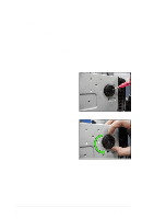
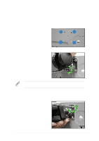
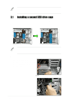
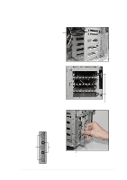
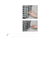
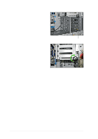
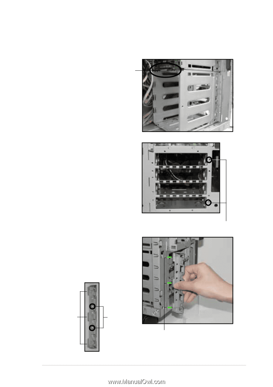
3. Make sure that the cage lock tab snaps to the bottom of the first drive cage. When properly installed, the cage should align with the first drive cage. Cage lock tab snapped securely to the bottom of first drive cage 4. From the front side, secure the right side of the cage with two screws. 5. Position the support bracket for the drive trays to the left side of the cage with the three protruding tabs matching the elongated holes on the chassis. Front screw holes Protruding tabs Screw holes SCSI drive tray support bracket ASUS AP1720-E1 barebone server Elongated holes for bracket 3-3
-
 1
1 -
2
-
3
-
4
-
5
-
6
-
7
-
8
-
9
-
10
-
11
-
12
-
13
-
14
-
15
-
16
-
17
-
18
-
19
-
20
-
21
-
22
-
23
-
24
-
25
-
26
-
27
-
28
-
29
-
30
-
31
-
32
-
33
-
34
-
35
-
36
-
37
-
38
-
39
-
40
-
41
-
42
-
43
-
44
-
45
-
46
-
47
-
48
-
49
-
50
-
51
-
52
-
53
-
54
-
55
-
56
-
57
-
58
-
59
-
60
-
61
-
62
-
63
-
 64
64 -
 65
65 -
 66
66 -
 67
67 -
 68
68 -
 69
69 -
 70
70 -
 71
71 -
 72
72 -
 73
73 -
 74
74 -
75
-
76
-
77
-
78
 |
 |
3-3
ASUS AP1720-E1 barebone server
3.
Make sure that the cage lock tab snaps to the bottom of the first drive
cage. When properly installed, the cage should align with the first drive
cage.
Cage lock tab snapped securely
to the bottom of first drive cage
4.
From the front side, secure the
right side of the cage with two
screws.
Front screw holes
5.
Position the support bracket for
the drive trays to the left side of
the cage with the three protruding
tabs matching the elongated
holes on the chassis.
SCSI drive tray support bracket
Protruding tabs
Screw holes
Elongated holes for bracket