Cisco 4948 Installation Guide - Page 101
Console Port - e 10g
 |
UPC - 746320908878
View all Cisco 4948 manuals
Add to My Manuals
Save this manual to your list of manuals |
Page 101 highlights
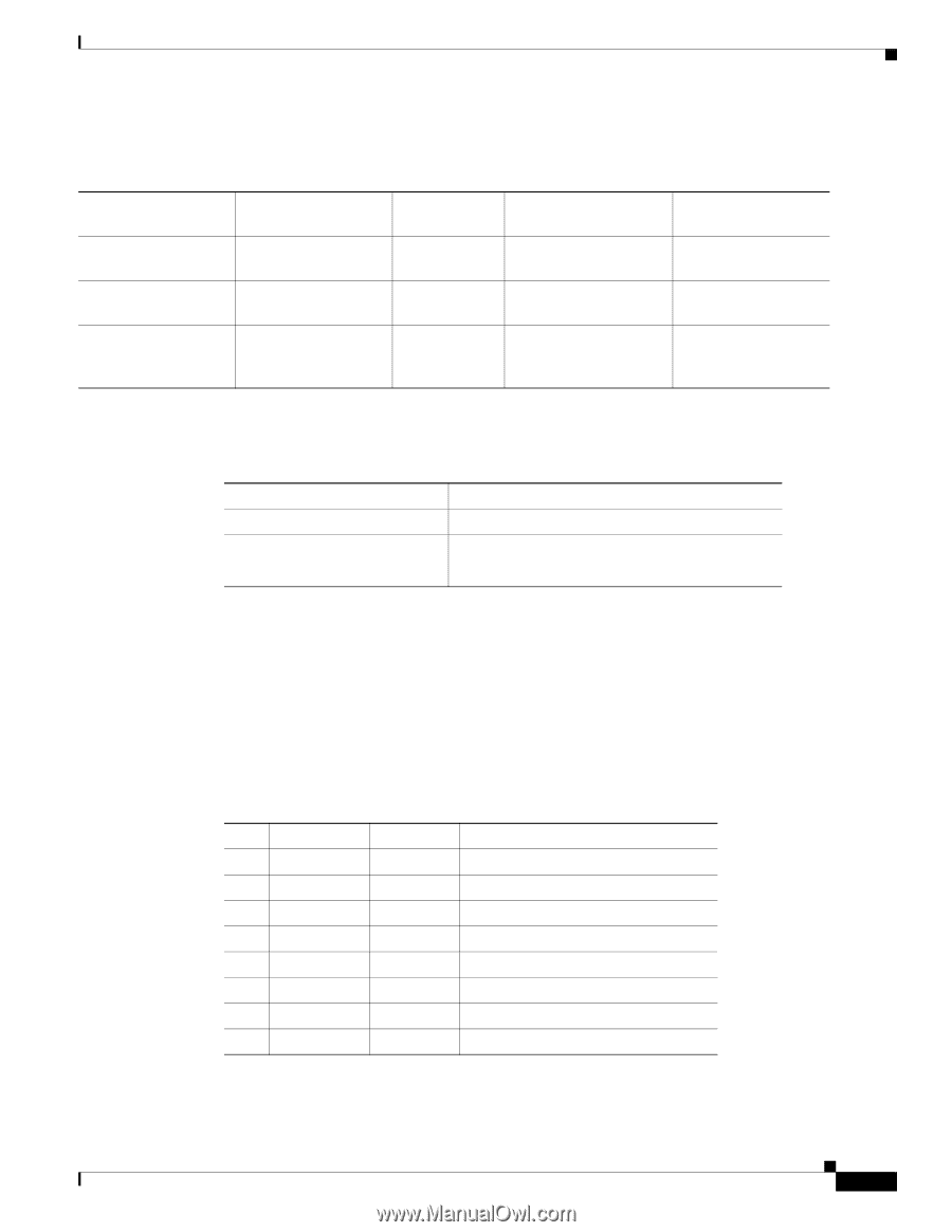
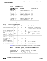
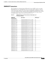
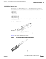
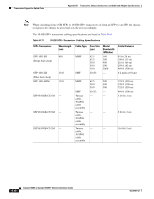
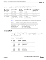
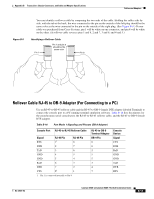
Appendix B Transceiver, Chassis Connectors, and Cable and Adapter Specifications Console Port Table B-12 lists the SFP+ transceiver optical transmit and receive specifications. Table B-12 SFP+ Transceiver Module Optical Transmit and Receive Specifications SFP+ Transceiver Module Model SFP-10G-SR SFP-10G-LR SFP-10G-LRM Transceiver Type 10GBASE-SR, 850-nm MMF 10GBASE-LR, 1310-nm SMF 10GBASE-LRM, 1310-nm MMF and SMF Transmit Power (dBm) -1.3 (Max) -7.3 (Min) 0.5 (Max) -8.2 (Min) 0.5 (Max) -6.5 (Min) Receive Power (dBm) -1.0 (Max) -9.9 (Min) 0.5 (Max) -14.4 (Min) 0.5 (Max) -8.4 (Min average) -6.4 (Min in OMA) Transmit and Receive Wavelength (nm) 840 to 860 1260 to 1355 1260 to 1355 Table B-13 lists the physical and environmental specifications for the 10-GB SFP+ transceivers. Table B-13 10-GB SFP+ Transceiver Physical and Environmental Specifications Item Dimensions (H x W x D) Operating temperature Storage temperature Specification 0.04 x 0.53 x 2.22 in. (8.5 x 13.4 x 56.5 mm) 32° to 122°F (0° to 50°C) -40° to 185°F (-40° to 85°C) Console Port Both the Catalyst 4948E and the Catalyst 4948E-F switches can be accessed through a serial console port located on the chassis front panel. The console port is 10/100/1000BASE-T port that uses an RJ-45 connector. The console port allows you to access the switch either locally (with a console terminal or PC) or remotely (with a modem). Table B-14 lists the console port pinouts. Table B-14 Console Port Pinouts Pin Signal 1 RTS 2 DTR 3 TXD 4 GND 5 GND 6 RXD 7 DSR 8 CTS Direction output output output - - input input input Description request to send data terminal ready transmit data - - receive data data set ready clear to send OL-21561-02 Catalyst 4948E an Catalyst 4948E-F Switch Installation Guide B-11
-
 1
1 -
2
-
3
-
4
-
5
-
6
-
7
-
8
-
9
-
10
-
11
-
12
-
13
-
14
-
15
-
16
-
17
-
18
-
19
-
20
-
21
-
22
-
23
-
24
-
25
-
26
-
27
-
28
-
29
-
30
-
31
-
32
-
33
-
34
-
35
-
36
-
37
-
38
-
39
-
40
-
41
-
42
-
43
-
44
-
45
-
46
-
47
-
48
-
49
-
50
-
51
-
52
-
53
-
54
-
55
-
56
-
57
-
58
-
59
-
60
-
61
-
62
-
63
-
64
-
65
-
66
-
67
-
68
-
69
-
70
-
71
-
72
-
73
-
74
-
75
-
76
-
77
-
78
-
79
-
80
-
81
-
82
-
83
-
84
-
85
-
86
-
87
-
88
-
89
-
90
-
91
-
92
-
93
-
94
-
95
-
 96
96 -
 97
97 -
 98
98 -
 99
99 -
 100
100 -
 101
101 -
 102
102 -
 103
103 -
 104
104 -
 105
105 -
 106
106 -
107
-
108
-
109
-
110
-
111
-
112
-
113
-
114
-
115
-
116
-
117
-
118
-
119
-
120
-
121
-
122
-
123
-
124
-
125
-
126
-
127
-
128
-
129
-
130
-
131
-
132
-
133
-
134
-
135
-
136
-
137
-
138
-
139
-
140
-
141
-
142
-
143
-
144
-
145
-
146
-
147
-
148
-
149
-
150
-
151
-
152
-
153
-
154
-
155
-
156
-
157
-
158
-
159
-
160
-
161
-
162
 |
 |