Cisco 4948 Installation Guide - Page 62
Connecting to the Ethernet Management Port, Connecting to the Console Port - router
 |
UPC - 746320908878
View all Cisco 4948 manuals
Add to My Manuals
Save this manual to your list of manuals |
Page 62 highlights
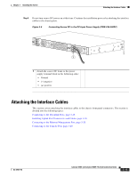
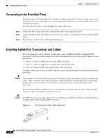
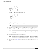
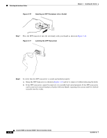
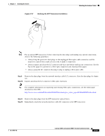
Attaching the Interface Cables Chapter 3 Installing the Switch Step 13 To connect 1000BASE-T SFP transceivers to a copper network, follow these substeps: Caution To comply with GR-1089 intrabuilding lightning immunity requirements, you must use grounded, shielded, twisted-pair Category 5 cabling. a. Insert the Category 5 network cable RJ-45 connector into the SFP transceiver RJ-45 connector. Note When connecting to a 1000BASE-T-compatible server, workstation, or router, use four twisted-pair, straight-through Category 5 cabling for the SFP transceiver port. When connecting to a 1000BASE-T-compatible switch or repeater, use four twisted-pair, crossover Category 5 cabling. b. Insert the other end of the network cable into an RJ-45 connector on a 1000BASE-T-compatible target device. Connecting to the Ethernet Management Port Both chassis provide a Ethernet Management port that can be used to manage the switch through an Ethernet network. This port can also be used to download software to the switch or transfer files to remote servers for analysis or backup storage. The typical connection to the Management Ethernet port uses an Ethernet cable with RJ-45 connectors at each end. The other end of the cable typically connects to an Ethernet switch, hub, or router that provides connectivity between the multishelf system and networks from which system management is desired. To attach a cable to the Ethernet management port, follow these steps: Step 1 Step 2 Connect the RJ-45 plug at one end of the network cable to the target device port. Connect the RJ-45 plug at the other end of the network cable to a Ethernet Management port on the Catalyst 4948E chassis. Connecting to the Console Port You must use the console port to perform the initial configuration. To connect the switch console port to a PC, use an RJ-45-to-DB-9 adapter cable (optional). To connect the PC or terminal to the Catalyst 4948E switch console port, follow these steps: Step 1 Step 2 Using an RJ-45-to-DB-9 adapter cable, insert the RJ-45 connector into the console port that is located on the front of the switch. Attach the DB-9 female DTE of the adapter cable to a PC serial port, or attach an appropriate adapter to the terminal. 3-20 Catalyst 4948E and Catalyst 4948E-F Switch Installation Guide OL-21561-02
-
 1
1 -
2
-
3
-
4
-
5
-
6
-
7
-
8
-
9
-
10
-
11
-
12
-
13
-
14
-
15
-
16
-
17
-
18
-
19
-
20
-
21
-
22
-
23
-
24
-
25
-
26
-
27
-
28
-
29
-
30
-
31
-
32
-
33
-
34
-
35
-
36
-
37
-
38
-
39
-
40
-
41
-
42
-
43
-
44
-
45
-
46
-
47
-
48
-
49
-
50
-
51
-
52
-
53
-
54
-
55
-
56
-
 57
57 -
 58
58 -
 59
59 -
 60
60 -
 61
61 -
 62
62 -
 63
63 -
 64
64 -
 65
65 -
 66
66 -
 67
67 -
68
-
69
-
70
-
71
-
72
-
73
-
74
-
75
-
76
-
77
-
78
-
79
-
80
-
81
-
82
-
83
-
84
-
85
-
86
-
87
-
88
-
89
-
90
-
91
-
92
-
93
-
94
-
95
-
96
-
97
-
98
-
99
-
100
-
101
-
102
-
103
-
104
-
105
-
106
-
107
-
108
-
109
-
110
-
111
-
112
-
113
-
114
-
115
-
116
-
117
-
118
-
119
-
120
-
121
-
122
-
123
-
124
-
125
-
126
-
127
-
128
-
129
-
130
-
131
-
132
-
133
-
134
-
135
-
136
-
137
-
138
-
139
-
140
-
141
-
142
-
143
-
144
-
145
-
146
-
147
-
148
-
149
-
150
-
151
-
152
-
153
-
154
-
155
-
156
-
157
-
158
-
159
-
160
-
161
-
162
 |
 |