Cisco 4948 Installation Guide - Page 32
Air Flow, If the ambient intake air temperature exceeds 104°F 40°C - power requirements
 |
UPC - 746320908878
View all Cisco 4948 manuals
Add to My Manuals
Save this manual to your list of manuals |
Page 32 highlights
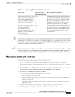
Site Requirements Chapter 2 Preparing for Installation • Allow a 2-hour warm-up period to bring the chassis up to normal operating temperature before turning it on for chassis that have been exposed to abnormally cold temperatures. Failure to observe these guidelines can damage internal chassis components. Note The Catalyst 4948E and the Catalyst 4948E-F switches are equipped with internal air temperature sensors that are triggered at 104°F (40°C) generating a minor alarm and at 131°F (55°C) generating a major alarm. Air Flow The Catalyst 4948E and Catalyst 4948E-F switches are designed to be installed in an environment where there is a sufficient volume of air available to cool the chassis and the power supplies. Any constraints placed on the free flow of air through the chassis or an elevated ambient air temperature can cause the switch to overheat and shut down. To maintain proper air circulation through the switch chassis, we recommend that you maintain a minimum 6-inch (15 cm) separation between a wall and the chassis hot air exhaust. Failure to maintain adequate spacing between chassis can cause the switch chassis that is drawing in the hot exhaust air to overheat and fail. If you are installing your Catalyst 4948E or Catalyst 4948E-F switch chassis in an enclosed or partially enclosed rack, we strongly recommend that you verify that your site meets the following guidelines: • Verify that the ambient air temperature within the enclosed or partially enclosed rack is within the chassis operating temperature limits. After installing the chassis in the rack, power up the chassis and allow the chassis temperature to stabilize (approximately 2 hours). Measure the ambient air temperature at the chassis air intake grill and at the chassis air exhaust grill by positioning an external temperature probe approximately 1 inch (2.5 cm) away from the grills. - If the ambient intake air temperature is less than 104°F (40°C), the rack meets the intake air temperature criterion. - If the ambient intake air temperature exceeds 104°F (40°C), the system might experience minor temperature alarms and is in danger of overheating. - If the ambient intake air temperature equals or is greater than 131°F (55°C), the system will experience a major temperature alarm and shut down. • Verify that the enclosed or partially enclosed rack allows an adequate flow of air through the switch chassis as follows: - If the difference between the measured intake air temperature and the exhaust air temperature does not exceed 10°C, there is sufficient airflow in the rack. - If the difference in air temperature exceeds 10°C, there is insufficient airflow to cool the chassis. Note The 10°C temperature differential between the intake and the exhaust must be determined by taking measurements using external digital temperature probes. Do not use the chassis internal temperature sensors to measure the temperature differential. Catalyst 4948E and Catalyst 4948E-F Switch Installation Guide 2-4 OL-21561-02
-
 1
1 -
2
-
3
-
4
-
5
-
6
-
7
-
8
-
9
-
10
-
11
-
12
-
13
-
14
-
15
-
16
-
17
-
18
-
19
-
20
-
21
-
22
-
23
-
24
-
25
-
26
-
 27
27 -
 28
28 -
 29
29 -
 30
30 -
 31
31 -
 32
32 -
 33
33 -
 34
34 -
 35
35 -
 36
36 -
 37
37 -
38
-
39
-
40
-
41
-
42
-
43
-
44
-
45
-
46
-
47
-
48
-
49
-
50
-
51
-
52
-
53
-
54
-
55
-
56
-
57
-
58
-
59
-
60
-
61
-
62
-
63
-
64
-
65
-
66
-
67
-
68
-
69
-
70
-
71
-
72
-
73
-
74
-
75
-
76
-
77
-
78
-
79
-
80
-
81
-
82
-
83
-
84
-
85
-
86
-
87
-
88
-
89
-
90
-
91
-
92
-
93
-
94
-
95
-
96
-
97
-
98
-
99
-
100
-
101
-
102
-
103
-
104
-
105
-
106
-
107
-
108
-
109
-
110
-
111
-
112
-
113
-
114
-
115
-
116
-
117
-
118
-
119
-
120
-
121
-
122
-
123
-
124
-
125
-
126
-
127
-
128
-
129
-
130
-
131
-
132
-
133
-
134
-
135
-
136
-
137
-
138
-
139
-
140
-
141
-
142
-
143
-
144
-
145
-
146
-
147
-
148
-
149
-
150
-
151
-
152
-
153
-
154
-
155
-
156
-
157
-
158
-
159
-
160
-
161
-
162
 |
 |