Cisco 4948 Installation Guide - Page 27
Front Panel LEDs - s 48
 |
UPC - 746320908878
View all Cisco 4948 manuals
Add to My Manuals
Save this manual to your list of manuals |
Page 27 highlights
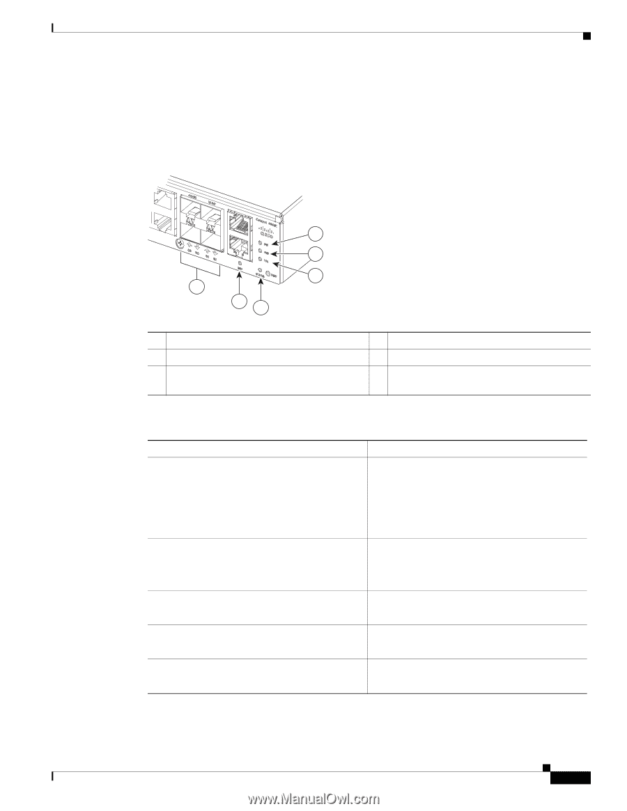
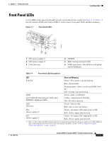
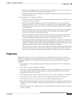
Chapter 1 Product Overview Front Panel LEDs Front Panel LEDs A set of LEDs on the chassis front panel provide visual status for the switch. (See Figure 1-7.) Table 1-4 lists the Catalyst 4948E and Catalyst 4948E-F switch chassis front panel LEDs and their meanings. Figure 1-7 Front Panel LEDs OL-21561-02 1 2 3 6 54 1 PS1 (power supply 1) 2 PS2 (power supply 2) 3 FAN (fan tray) 278086 4 STATUS 5 MGT (management port LED) 6 LINK (port status). One LED for each uplink and downlink port. Table 1-4 Front Panel LED Descriptions LED State and Meaning STATUS Green-The system is up and running. Red-System fault. Flashing amber-Power-on self-test (POST) boot up. Off-System is not powered up. LINK Green-Link is established. 48 10/100/1000 downlink port LEDs and 4 SFP/SFP+ uplink port LEDs Amber-Administrative disabled. Off-No link is detected. FAN (Fan tray) Green-Fan tray OK. Red-One or more fan failures. PS1 (Power supply 1)1 Green-AC-input or DC-input power is OK. Red-Power supply fault detected. PS2 (Power supply 2)1 Green-AC-input or DC-input power is OK. Red-Power supply fault detected. 1. There are three additional LEDs mounted on the power supply front panel that provide power supply status. These LEDs are only visible from the back of the chassis. For a description of the LEDs, see the "300 W AC-Input Power Supply (PWR-C49E-300AC-R)" section on page A-1. Catalyst 4948E and Catalyst 4948E-F Switch Installation Guide 1-11
-
 1
1 -
2
-
3
-
4
-
5
-
6
-
7
-
8
-
9
-
10
-
11
-
12
-
13
-
14
-
15
-
16
-
17
-
18
-
19
-
20
-
21
-
 22
22 -
 23
23 -
 24
24 -
 25
25 -
 26
26 -
 27
27 -
 28
28 -
 29
29 -
 30
30 -
 31
31 -
 32
32 -
33
-
34
-
35
-
36
-
37
-
38
-
39
-
40
-
41
-
42
-
43
-
44
-
45
-
46
-
47
-
48
-
49
-
50
-
51
-
52
-
53
-
54
-
55
-
56
-
57
-
58
-
59
-
60
-
61
-
62
-
63
-
64
-
65
-
66
-
67
-
68
-
69
-
70
-
71
-
72
-
73
-
74
-
75
-
76
-
77
-
78
-
79
-
80
-
81
-
82
-
83
-
84
-
85
-
86
-
87
-
88
-
89
-
90
-
91
-
92
-
93
-
94
-
95
-
96
-
97
-
98
-
99
-
100
-
101
-
102
-
103
-
104
-
105
-
106
-
107
-
108
-
109
-
110
-
111
-
112
-
113
-
114
-
115
-
116
-
117
-
118
-
119
-
120
-
121
-
122
-
123
-
124
-
125
-
126
-
127
-
128
-
129
-
130
-
131
-
132
-
133
-
134
-
135
-
136
-
137
-
138
-
139
-
140
-
141
-
142
-
143
-
144
-
145
-
146
-
147
-
148
-
149
-
150
-
151
-
152
-
153
-
154
-
155
-
156
-
157
-
158
-
159
-
160
-
161
-
162
 |
 |