Cisco 4948 Installation Guide - Page 74
Removing and Installing the Fan Tray, Required Tools, Removing the Fan Tray
 |
UPC - 746320908878
View all Cisco 4948 manuals
Add to My Manuals
Save this manual to your list of manuals |
Page 74 highlights
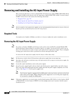
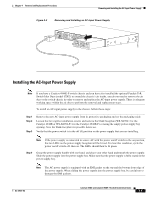
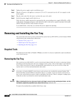
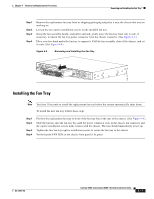
Removing and Installing the Fan Tray Chapter 4 Removal and Replacement Procedures Step 5 Step 6 Step 7 Step 8 Tighten the power supply captive installation screw. Plug the AC power cord appliance connector (C15 or C13 connector) into the AC-in receptacle on the power supply. Plug the other end of the AC power cord into the source AC outlet. Switch the power supply on/off switch to on. Verify the power supply operation by ensuring that the corresponding power supply LED (PS1 or PS2) on the chassis front panel is lit green. Also check the LEDs on the power supply front panel. Both LEDs (INPUT OK and OUTPUT OK) should be lit green. As an added check, verify that you can hear the power supply fan operating. Removing and Installing the Fan Tray This section describes how to remove and install the system fan tray (WS-X4993=) in the Catalyst 4948E switch chassis and contains these subsections: • Required Tools, page 4-10 • Removing the Fan Tray, page 4-10 • Installing the Fan Tray, page 4-11 Required Tools You might need a flat-blade or Number 2 Phillips screwdriver to loosen or tighten the captive installation screw on the fan tray. Removing the Fan Tray The system fan tray (WS-X4993=) can be removed and replaced while the system is operating without presenting an electrical hazard to the user or damage to the system. A 30-second window is provided for you to remove the defective fan tray and install the replacement tray. If you exceed 30 seconds, the system starts to overheat and automatically shuts down. Note If you have a Catalyst 4948E-F switch chassis and you have also installed the optional Panduit ToR Switch Inlet Duct (model CDE2) to extend the chassis's air intake, you do not need to remove the air duct or the switch chassis in order to remove and replace the fan tray. There is adequate working space within the air duct to perform the removal and replacement steps. Warning When removing the fan tray, keep your hands and fingers away from the spinning fan blades. Let the fan blades completely stop before you remove the fan tray. Statement 258 To remove the installed fan assembly, follow these steps: 4-10 Catalyst 4948E and Catalyst 4948E-F Switch Installation Guide OL-21561-02
-
 1
1 -
2
-
3
-
4
-
5
-
6
-
7
-
8
-
9
-
10
-
11
-
12
-
13
-
14
-
15
-
16
-
17
-
18
-
19
-
20
-
21
-
22
-
23
-
24
-
25
-
26
-
27
-
28
-
29
-
30
-
31
-
32
-
33
-
34
-
35
-
36
-
37
-
38
-
39
-
40
-
41
-
42
-
43
-
44
-
45
-
46
-
47
-
48
-
49
-
50
-
51
-
52
-
53
-
54
-
55
-
56
-
57
-
58
-
59
-
60
-
61
-
62
-
63
-
64
-
65
-
66
-
67
-
68
-
 69
69 -
 70
70 -
 71
71 -
 72
72 -
 73
73 -
 74
74 -
 75
75 -
 76
76 -
 77
77 -
 78
78 -
 79
79 -
80
-
81
-
82
-
83
-
84
-
85
-
86
-
87
-
88
-
89
-
90
-
91
-
92
-
93
-
94
-
95
-
96
-
97
-
98
-
99
-
100
-
101
-
102
-
103
-
104
-
105
-
106
-
107
-
108
-
109
-
110
-
111
-
112
-
113
-
114
-
115
-
116
-
117
-
118
-
119
-
120
-
121
-
122
-
123
-
124
-
125
-
126
-
127
-
128
-
129
-
130
-
131
-
132
-
133
-
134
-
135
-
136
-
137
-
138
-
139
-
140
-
141
-
142
-
143
-
144
-
145
-
146
-
147
-
148
-
149
-
150
-
151
-
152
-
153
-
154
-
155
-
156
-
157
-
158
-
159
-
160
-
161
-
162
 |
 |