Cisco 4948 Installation Guide - Page 107
LED Readings, LED and Color, Meaning
 |
UPC - 746320908878
View all Cisco 4948 manuals
Add to My Manuals
Save this manual to your list of manuals |
Page 107 highlights
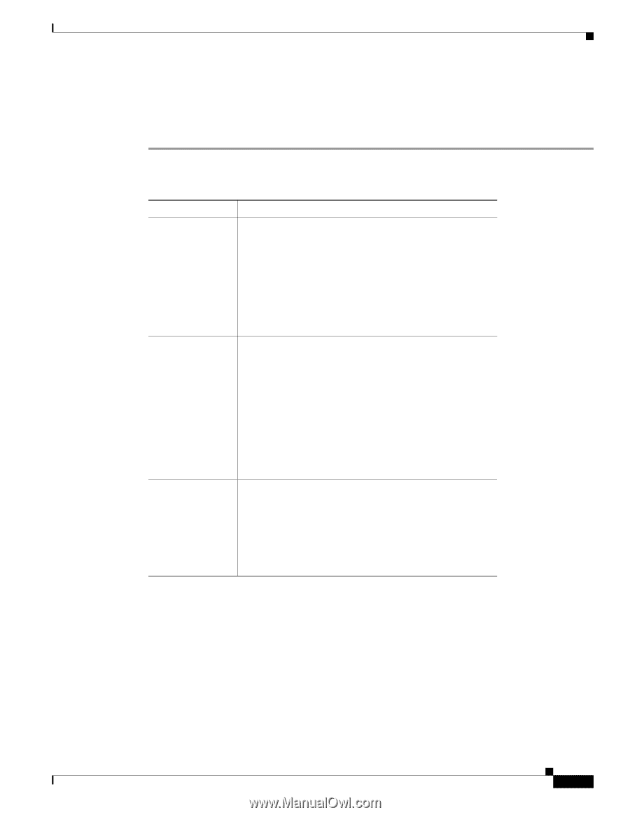
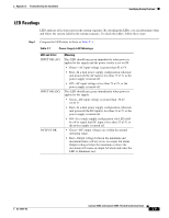
Appendix C Troubleshooting the Installation Identifying Startup Problems LED Readings LEDs indicate all system states in the startup sequence. By checking the LEDs, you can determine when and where the system failed in the startup sequence. To check the LEDs, follow these steps: Step 1 Compare the LED states to those in Table C-1. Table C-1 Power Supply LED Meanings LED and Color INPUT OK (AC) INPUT OK (DC) OUTPUT OK Meaning This LED should turn green immediately when power is applied to the supply and the power switch is set to ON. • Green-AC input voltage is greater than 82 ±3 V. • Red-In a dual power supply configuration (alternate unit powered) the AC input is less than 73 ±3 V, or the power supply is turned off. • Off-AC input voltage is less than 73 ±3 V, or the power supply is turned off. This LED should turn green immediately when power is applied to the supply. • Green-DC input voltage is greater than -38.25 ±2.25 V. • Red-In a dual power supply configuration (alternate unit powered) the DC input is less than 33 ±3 V, or the power supply is turned off. • Off-In a single supply configuration, the LED shall be off to signal that DC input is less than 33 ±3 V, or the power supply is turned off. • Green-DC output voltages are within the normal operating range. • Red-Output voltage between the minimum and maximum limits will not create an output fail alarm. Output voltages below the minimum or above the maximum will create an output fail alarm and cause the LED to illuminate red. OL-21561-02 Catalyst 4948E and Catalyst 4948E-F Switch Installation Guide C-3
-
 1
1 -
2
-
3
-
4
-
5
-
6
-
7
-
8
-
9
-
10
-
11
-
12
-
13
-
14
-
15
-
16
-
17
-
18
-
19
-
20
-
21
-
22
-
23
-
24
-
25
-
26
-
27
-
28
-
29
-
30
-
31
-
32
-
33
-
34
-
35
-
36
-
37
-
38
-
39
-
40
-
41
-
42
-
43
-
44
-
45
-
46
-
47
-
48
-
49
-
50
-
51
-
52
-
53
-
54
-
55
-
56
-
57
-
58
-
59
-
60
-
61
-
62
-
63
-
64
-
65
-
66
-
67
-
68
-
69
-
70
-
71
-
72
-
73
-
74
-
75
-
76
-
77
-
78
-
79
-
80
-
81
-
82
-
83
-
84
-
85
-
86
-
87
-
88
-
89
-
90
-
91
-
92
-
93
-
94
-
95
-
96
-
97
-
98
-
99
-
100
-
101
-
 102
102 -
 103
103 -
 104
104 -
 105
105 -
 106
106 -
 107
107 -
 108
108 -
 109
109 -
 110
110 -
 111
111 -
 112
112 -
113
-
114
-
115
-
116
-
117
-
118
-
119
-
120
-
121
-
122
-
123
-
124
-
125
-
126
-
127
-
128
-
129
-
130
-
131
-
132
-
133
-
134
-
135
-
136
-
137
-
138
-
139
-
140
-
141
-
142
-
143
-
144
-
145
-
146
-
147
-
148
-
149
-
150
-
151
-
152
-
153
-
154
-
155
-
156
-
157
-
158
-
159
-
160
-
161
-
162
 |
 |