Cisco 4948 Installation Guide - Page 42
Task No., Planning Activity, Verified By, Table 2-2, Site Planning Checklist - e rfi
 |
UPC - 746320908878
View all Cisco 4948 manuals
Add to My Manuals
Save this manual to your list of manuals |
Page 42 highlights
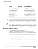
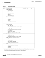
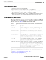
Site Preparation Checklist Chapter 2 Preparing for Installation Table 2-2 Site Planning Checklist Task No. Planning Activity Verified By Time Date 1 Space evaluation: • Space and layout • Floor covering • Impact and vibration • Lighting • Maintenance access 2 Environmental evaluation: • Ambient temperature • Humidity • Altitude • Atmospheric contamination • Airflow 3 Power evaluation: • Input power type • Power receptacles (Depends on power supply)1 • Receptacle proximity to the equipment • Dedicated (separate) circuits for redundant power supplies • UPS for power failures2 • DC systems: Proper gauge wire and lugs 4 Grounding evaluation: • Circuit breaker size • CO ground (AC- and DC-powered systems) 5 Cable and interface equipment evaluation: • Cable type • Connector type • Cable distance limitations • Interface equipment (transceivers) 6 EMI evaluation: • Distance limitations for signaling • Site wiring • RFI levels 1. Verify that each power supply installed in the chassis has a dedicated AC source or DC source circuit. 2. Refer to the power supply's kVA rating as a sizing criteria in determining the output required by the UPS. The power supply's kVA rating value is listed in the specifications table for each power supply in Appendix A. 2-14 Catalyst 4948E and Catalyst 4948E-F Switch Installation Guide OL-21561-02
-
 1
1 -
2
-
3
-
4
-
5
-
6
-
7
-
8
-
9
-
10
-
11
-
12
-
13
-
14
-
15
-
16
-
17
-
18
-
19
-
20
-
21
-
22
-
23
-
24
-
25
-
26
-
27
-
28
-
29
-
30
-
31
-
32
-
33
-
34
-
35
-
36
-
 37
37 -
 38
38 -
 39
39 -
 40
40 -
 41
41 -
 42
42 -
 43
43 -
 44
44 -
 45
45 -
 46
46 -
 47
47 -
48
-
49
-
50
-
51
-
52
-
53
-
54
-
55
-
56
-
57
-
58
-
59
-
60
-
61
-
62
-
63
-
64
-
65
-
66
-
67
-
68
-
69
-
70
-
71
-
72
-
73
-
74
-
75
-
76
-
77
-
78
-
79
-
80
-
81
-
82
-
83
-
84
-
85
-
86
-
87
-
88
-
89
-
90
-
91
-
92
-
93
-
94
-
95
-
96
-
97
-
98
-
99
-
100
-
101
-
102
-
103
-
104
-
105
-
106
-
107
-
108
-
109
-
110
-
111
-
112
-
113
-
114
-
115
-
116
-
117
-
118
-
119
-
120
-
121
-
122
-
123
-
124
-
125
-
126
-
127
-
128
-
129
-
130
-
131
-
132
-
133
-
134
-
135
-
136
-
137
-
138
-
139
-
140
-
141
-
142
-
143
-
144
-
145
-
146
-
147
-
148
-
149
-
150
-
151
-
152
-
153
-
154
-
155
-
156
-
157
-
158
-
159
-
160
-
161
-
162
 |
 |