Cisco 4948 Installation Guide - Page 46
Verifying Package Contents, Required Tools, No. 2 Phillips screwdriver - rack kit
 |
UPC - 746320908878
View all Cisco 4948 manuals
Add to My Manuals
Save this manual to your list of manuals |
Page 46 highlights
Preparing to Install the Chassis Chapter 3 Installing the Switch Verifying Package Contents Carefully remove the chassis and accessory kit from the shipping container, and check each item for damage. If any item is missing or damaged, contact your Cisco representative or reseller for support. Return all packing material to the shipping container, and save it. The chassis is shipped with these items in the accessory kit: • One RJ-45 female-to-DB-9 female adapter plug • System ground kit • Rack-mounting kit that contains the following items: - Two 19-inch rack-mounting brackets - Eight M4 x 8 mm Phillips flat-head screws for attaching the brackets to the switch - Four 12-24 x 3/4-inch and four 10-32 x 3/4-inch Phillips machine screws for attaching the rack-mount brackets to a rack - Disposable ESD wrist strap Note A console cable is not provided in the accessory kit. It can ordered as an option. Required Tools To properly install the chassis, you need the following tools and equipment: • No. 1 Phillips screwdriver • No. 2 Phillips screwdriver • 3/16-inch flat-blade screwdriver • Antistatic mat or antistatic foam • Your own ESD grounding strap or the disposable ESD strap included with the system • Tape measure and level • Copper system ground wire (the required wire gauge is determined by local or national electrical codes) • Source DC power cables (the required wire gauge is determined by local or national electrical codes) • Either insulated crimp-on spade lugs or insulated crimp-on ring connectors (the required size and style is determined by local or national electrical codes) • Wire-stripping tool • Crimping tool Catalyst 4948E and Catalyst 4948E-F Switch Installation Guide 3-4 OL-21561-02
-
 1
1 -
2
-
3
-
4
-
5
-
6
-
7
-
8
-
9
-
10
-
11
-
12
-
13
-
14
-
15
-
16
-
17
-
18
-
19
-
20
-
21
-
22
-
23
-
24
-
25
-
26
-
27
-
28
-
29
-
30
-
31
-
32
-
33
-
34
-
35
-
36
-
37
-
38
-
39
-
40
-
 41
41 -
 42
42 -
 43
43 -
 44
44 -
 45
45 -
 46
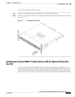
46 -
 47
47 -
 48
48 -
 49
49 -
 50
50 -
 51
51 -
52
-
53
-
54
-
55
-
56
-
57
-
58
-
59
-
60
-
61
-
62
-
63
-
64
-
65
-
66
-
67
-
68
-
69
-
70
-
71
-
72
-
73
-
74
-
75
-
76
-
77
-
78
-
79
-
80
-
81
-
82
-
83
-
84
-
85
-
86
-
87
-
88
-
89
-
90
-
91
-
92
-
93
-
94
-
95
-
96
-
97
-
98
-
99
-
100
-
101
-
102
-
103
-
104
-
105
-
106
-
107
-
108
-
109
-
110
-
111
-
112
-
113
-
114
-
115
-
116
-
117
-
118
-
119
-
120
-
121
-
122
-
123
-
124
-
125
-
126
-
127
-
128
-
129
-
130
-
131
-
132
-
133
-
134
-
135
-
136
-
137
-
138
-
139
-
140
-
141
-
142
-
143
-
144
-
145
-
146
-
147
-
148
-
149
-
150
-
151
-
152
-
153
-
154
-
155
-
156
-
157
-
158
-
159
-
160
-
161
-
162
 |
 |