Cisco 4948 Installation Guide - Page 65
Removal and Replacement Procedures - 4948e configuration example
 |
UPC - 746320908878
View all Cisco 4948 manuals
Add to My Manuals
Save this manual to your list of manuals |
Page 65 highlights
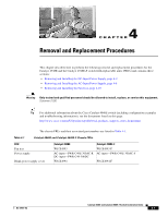
4 C H A P T E R Removal and Replacement Procedures This chapter describes how to perform the following removal and replacement procedures for the Catalyst 4948E and the Catalyst 4948E-F switch field-replaceable units (FRUs) and contains these sections: • Removing and Installing the DC-Input Power Supply, page 4-2 • Removing and Installing the AC-Input Power Supply, page 4-8 • Removing and Installing the Fan Tray, page 4-10 Warning Only trained and qualified personnel should be allowed to install, replace, or service this equipment. Statement 1030 Tip For additional information about the Cisco Catalyst 4948E switch (including configuration examples and troubleshooting information), see the documents listed on this page: http://www.cisco.com/en/US/products/ps6021/tsd_products_support_series_home.html The chassis FRUs and their associated part numbers are listed in Table 4-1. Table 4-1 Catalyst 4948E and Catalyst 4948E-F Chassis FRUs FRU Fan tray Power supply Blank power supply cover Catalyst 4948E WS-X4993 AC-input-PWR-C49E-300AC-R DC-input-PWR-C49-300DC WS-X4994 Catalyst 4948E-F WS-X4993-F AC-input-PWR-C49E-300AC-F WS-X4994-F OL-21561-02 Catalyst 4948E and Catalyst 4948E-F Switch Installation Guide 4-1
-
 1
1 -
2
-
3
-
4
-
5
-
6
-
7
-
8
-
9
-
10
-
11
-
12
-
13
-
14
-
15
-
16
-
17
-
18
-
19
-
20
-
21
-
22
-
23
-
24
-
25
-
26
-
27
-
28
-
29
-
30
-
31
-
32
-
33
-
34
-
35
-
36
-
37
-
38
-
39
-
40
-
41
-
42
-
43
-
44
-
45
-
46
-
47
-
48
-
49
-
50
-
51
-
52
-
53
-
54
-
55
-
56
-
57
-
58
-
59
-
 60
60 -
 61
61 -
 62
62 -
 63
63 -
 64
64 -
 65
65 -
 66
66 -
 67
67 -
 68
68 -
 69
69 -
 70
70 -
71
-
72
-
73
-
74
-
75
-
76
-
77
-
78
-
79
-
80
-
81
-
82
-
83
-
84
-
85
-
86
-
87
-
88
-
89
-
90
-
91
-
92
-
93
-
94
-
95
-
96
-
97
-
98
-
99
-
100
-
101
-
102
-
103
-
104
-
105
-
106
-
107
-
108
-
109
-
110
-
111
-
112
-
113
-
114
-
115
-
116
-
117
-
118
-
119
-
120
-
121
-
122
-
123
-
124
-
125
-
126
-
127
-
128
-
129
-
130
-
131
-
132
-
133
-
134
-
135
-
136
-
137
-
138
-
139
-
140
-
141
-
142
-
143
-
144
-
145
-
146
-
147
-
148
-
149
-
150
-
151
-
152
-
153
-
154
-
155
-
156
-
157
-
158
-
159
-
160
-
161
-
162
 |
 |