Cisco 4948 Installation Guide - Page 24
Fan Tray, Catalyst 4948E Fan Tray (WS-X4993=) - power
 |
UPC - 746320908878
View all Cisco 4948 manuals
Add to My Manuals
Save this manual to your list of manuals |
Page 24 highlights
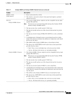
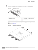
Fan Tray Chapter 1 Product Overview Fan Tray Both the Catalyst 4948E and the Catalyst 4948E-F switch chassis have a fan tray that is mounted in the rear of the chassis between the two power supplies. The Catalyst 4948E chassis fan tray (WS-X4993=) provides front-to-back air flow in the chassis and has a front panel that is color-coded dark grey. The Catalyst 4948E-F chassis fan tray (WS-X4993-F=) provides back-to-front air flow and has a front panel that is color-coded blue. Note The two fan trays are not interchangeable between the Catalyst 4948E and the Catalyst 4948E-F chassis. The WS-X4993-F fan tray is keyed to prevent insertion in the Catalyst 4948E chassis. Individual fan speed within the fan trays is controlled by redundant temperature sensors located at the air flow inlet (in the front of the chassis for the Catalyst 4948E and in the rear of the chassis for the Catalyst 4948E-F). There are six programmable temperature thresholds that trigger fan speed change. If there is an individual fan failure, the fan speed on the remaining fans is adjusted to try to compensate for the loss of the fan. Table 1-3 lists the fan speed settings and the associated temperature thresholds. Table 1-3 Fan Speeds Versus Chassis Temperature Thresholds Fan Speed PWM1 Duty Chassis Temperature Range Thresholds Setting Cycle Speed 0 41% T2-89.6°F (32°C) Note At T2, the fan speed increases to Speed 1. Speed 1 56% • T1-82.4°F (28°C) • T4-102.2°F (39°C) Note At T1, the fan speed decreases to Speed 0. At T4, the fan speed increases to Speed 2. Speed 2 75% T3-95.0°F (35°C) T6-116.6°F (47°C) Speed 32 100% Note At T3, the fan speed decreases to Speed 1. At T6, the fan speed increases to Speed 3. T5-Greater than 109.4°F (43°C) 1. Pulse-Width Modulation 2. Speed 3 is a fixed value and cannot be altered. Catalyst 4948E Fan Tray (WS-X4993=) The Catalyst 4948E fan tray (WS-X4993) contains four variable-speed, 12 VDC fans. (See Figure 1-3.) The fan tray is mounted in the rear of the chassis between the two power supplies. Note The WS-X4993 fan tray is not interchangeable with the WS-X4993-F fan tray. Catalyst 4948E and Catalyst 4948E-F Switch Installation Guide 1-8 OL-21561-02
-
 1
1 -
2
-
3
-
4
-
5
-
6
-
7
-
8
-
9
-
10
-
11
-
12
-
13
-
14
-
15
-
16
-
17
-
18
-
 19
19 -
 20
20 -
 21
21 -
 22
22 -
 23
23 -
 24
24 -
 25
25 -
 26
26 -
 27
27 -
 28
28 -
 29
29 -
30
-
31
-
32
-
33
-
34
-
35
-
36
-
37
-
38
-
39
-
40
-
41
-
42
-
43
-
44
-
45
-
46
-
47
-
48
-
49
-
50
-
51
-
52
-
53
-
54
-
55
-
56
-
57
-
58
-
59
-
60
-
61
-
62
-
63
-
64
-
65
-
66
-
67
-
68
-
69
-
70
-
71
-
72
-
73
-
74
-
75
-
76
-
77
-
78
-
79
-
80
-
81
-
82
-
83
-
84
-
85
-
86
-
87
-
88
-
89
-
90
-
91
-
92
-
93
-
94
-
95
-
96
-
97
-
98
-
99
-
100
-
101
-
102
-
103
-
104
-
105
-
106
-
107
-
108
-
109
-
110
-
111
-
112
-
113
-
114
-
115
-
116
-
117
-
118
-
119
-
120
-
121
-
122
-
123
-
124
-
125
-
126
-
127
-
128
-
129
-
130
-
131
-
132
-
133
-
134
-
135
-
136
-
137
-
138
-
139
-
140
-
141
-
142
-
143
-
144
-
145
-
146
-
147
-
148
-
149
-
150
-
151
-
152
-
153
-
154
-
155
-
156
-
157
-
158
-
159
-
160
-
161
-
162
 |
 |