Cisco 4948 Installation Guide - Page 55
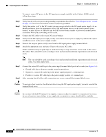
Connecting DC Source Power to the Switch - s replacement
 |
UPC - 746320908878
View all Cisco 4948 manuals
Add to My Manuals
Save this manual to your list of manuals |
Page 55 highlights
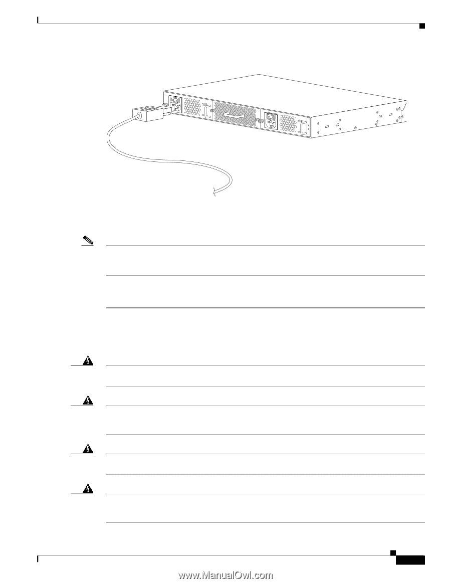
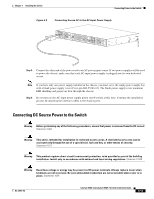
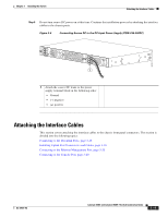
Chapter 3 Installing the Switch Connecting Power to the Switch Figure 3-5 Connecting Source AC to the AC-Input Power Supply PWR - 540 AC 100 7 240 VAC - 3A 50 - 60 Hz INPUT OK OUTPUT OK PWR - 540 AC 100 7 240 VAC - 3A 50 - 60 Hz INPUT OK OUTPUT OK 207518 Step 5 Connect the other end of the power cord to an AC-power input source. If two power supplies will be used to power the chassis, make sure that each AC-input power supply is plugged into its own dedicated circuit. Note If you have only one power supply installed in the chassis, you must cover the empty power supply bay with a blank power supply cover (Cisco p/n 800-25264-01). The blank power supply cover maintains EMI shielding and proper air flow through the chassis. Step 6 Do not turn on the AC-input power supply power on/off switch at this time. Continue the installation process by attaching the interface cables to the chassis ports. Connecting DC Source Power to the Switch Warning Before performing any of the following procedures, ensure that power is removed from the DC circuit. Statement 1003 Warning This unit is intended for installation in restricted access areas. A restricted access area can be accessed only through the use of a special tool, lock and key, or other means of security. Statement 1017 Warning This product requires short-circuit (overcurrent) protection, to be provided as part of the building installation. Install only in accordance with national and local wiring regulations. Statement 1045 Warning Hazardous voltage or energy may be present on DC power terminals. Always replace cover when terminals are not in service. Be sure uninsulated conductors are not accessible when cover is in place. Statement 1075 OL-21561-02 Catalyst 4948E and Catalyst 4948E-F Switch Installation Guide 3-13
-
 1
1 -
2
-
3
-
4
-
5
-
6
-
7
-
8
-
9
-
10
-
11
-
12
-
13
-
14
-
15
-
16
-
17
-
18
-
19
-
20
-
21
-
22
-
23
-
24
-
25
-
26
-
27
-
28
-
29
-
30
-
31
-
32
-
33
-
34
-
35
-
36
-
37
-
38
-
39
-
40
-
41
-
42
-
43
-
44
-
45
-
46
-
47
-
48
-
49
-
 50
50 -
 51
51 -
 52
52 -
 53
53 -
 54
54 -
 55
55 -
 56
56 -
 57
57 -
 58
58 -
 59
59 -
 60
60 -
61
-
62
-
63
-
64
-
65
-
66
-
67
-
68
-
69
-
70
-
71
-
72
-
73
-
74
-
75
-
76
-
77
-
78
-
79
-
80
-
81
-
82
-
83
-
84
-
85
-
86
-
87
-
88
-
89
-
90
-
91
-
92
-
93
-
94
-
95
-
96
-
97
-
98
-
99
-
100
-
101
-
102
-
103
-
104
-
105
-
106
-
107
-
108
-
109
-
110
-
111
-
112
-
113
-
114
-
115
-
116
-
117
-
118
-
119
-
120
-
121
-
122
-
123
-
124
-
125
-
126
-
127
-
128
-
129
-
130
-
131
-
132
-
133
-
134
-
135
-
136
-
137
-
138
-
139
-
140
-
141
-
142
-
143
-
144
-
145
-
146
-
147
-
148
-
149
-
150
-
151
-
152
-
153
-
154
-
155
-
156
-
157
-
158
-
159
-
160
-
161
-
162
 |
 |