Cisco 4948 Installation Guide - Page 17
Product Overview - power supply
 |
UPC - 746320908878
View all Cisco 4948 manuals
Add to My Manuals
Save this manual to your list of manuals |
Page 17 highlights
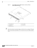
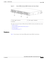
Product Overview 1 C H A P T E R Revised: January 4, 2012 Both the Catalyst 4948E switch and the Catalyst 4948E-F switch are 1-RU, horizontal, fixed-configuration chassis with 48 10/100/1000 downlink ports and 4 1-GB or 10-GB uplink ports. Both switches have one removable fan tray and support redundant power supplies. The primary difference between the two chassis is that the air flow in the Catalyst 4948E goes from the front of the chassis to the rear of the chassis while the air flow in the Catalyst 4948E-F goes from the rear of the chassis to the front of the chassis. Figure 1-1 shows the front view of both chassis with the major features identified and Figure 1-2 shows the rear view of both chassis with the major features identified. Note The fan trays and the power supplies are not interchangeable between the Catalyst 4948E and the Catalyst 4948E-F switch chassis. Tip For additional information about the Cisco Catalyst 4948E and the Catalyst 4948E-F switches (including configuration examples and troubleshooting information), see the documents listed on this page: http://www.cisco.com/en/US/products/ps6021/tsd_products_support_series_home.html OL-21561-02 Catalyst 4948E and Catalyst 4948E-F Switch Installation Guide 1-1
-
 1
1 -
2
-
3
-
4
-
5
-
6
-
7
-
8
-
9
-
10
-
11
-
 12
12 -
 13
13 -
 14
14 -
 15
15 -
 16
16 -
 17
17 -
 18
18 -
 19
19 -
 20
20 -
 21
21 -
 22
22 -
23
-
24
-
25
-
26
-
27
-
28
-
29
-
30
-
31
-
32
-
33
-
34
-
35
-
36
-
37
-
38
-
39
-
40
-
41
-
42
-
43
-
44
-
45
-
46
-
47
-
48
-
49
-
50
-
51
-
52
-
53
-
54
-
55
-
56
-
57
-
58
-
59
-
60
-
61
-
62
-
63
-
64
-
65
-
66
-
67
-
68
-
69
-
70
-
71
-
72
-
73
-
74
-
75
-
76
-
77
-
78
-
79
-
80
-
81
-
82
-
83
-
84
-
85
-
86
-
87
-
88
-
89
-
90
-
91
-
92
-
93
-
94
-
95
-
96
-
97
-
98
-
99
-
100
-
101
-
102
-
103
-
104
-
105
-
106
-
107
-
108
-
109
-
110
-
111
-
112
-
113
-
114
-
115
-
116
-
117
-
118
-
119
-
120
-
121
-
122
-
123
-
124
-
125
-
126
-
127
-
128
-
129
-
130
-
131
-
132
-
133
-
134
-
135
-
136
-
137
-
138
-
139
-
140
-
141
-
142
-
143
-
144
-
145
-
146
-
147
-
148
-
149
-
150
-
151
-
152
-
153
-
154
-
155
-
156
-
157
-
158
-
159
-
160
-
161
-
162
 |
 |